Laney SuperGroup in a pedal

This is a great sounding cranked Laney SuperGroup amp in a box similar to the Catalinbread Sabbra Cadabra. This is a J201 based effect and has the trimmers to set the desired voltages. More info on this layout can be found here.

There are a few layouts for this circuit and definitely worth the build. Now I need to get it boxed up.

Storyboardist also did a great 1590B / 125 layout with 9mm pots. I am waiting for the pots to verify this build. Here are the details on that layout.

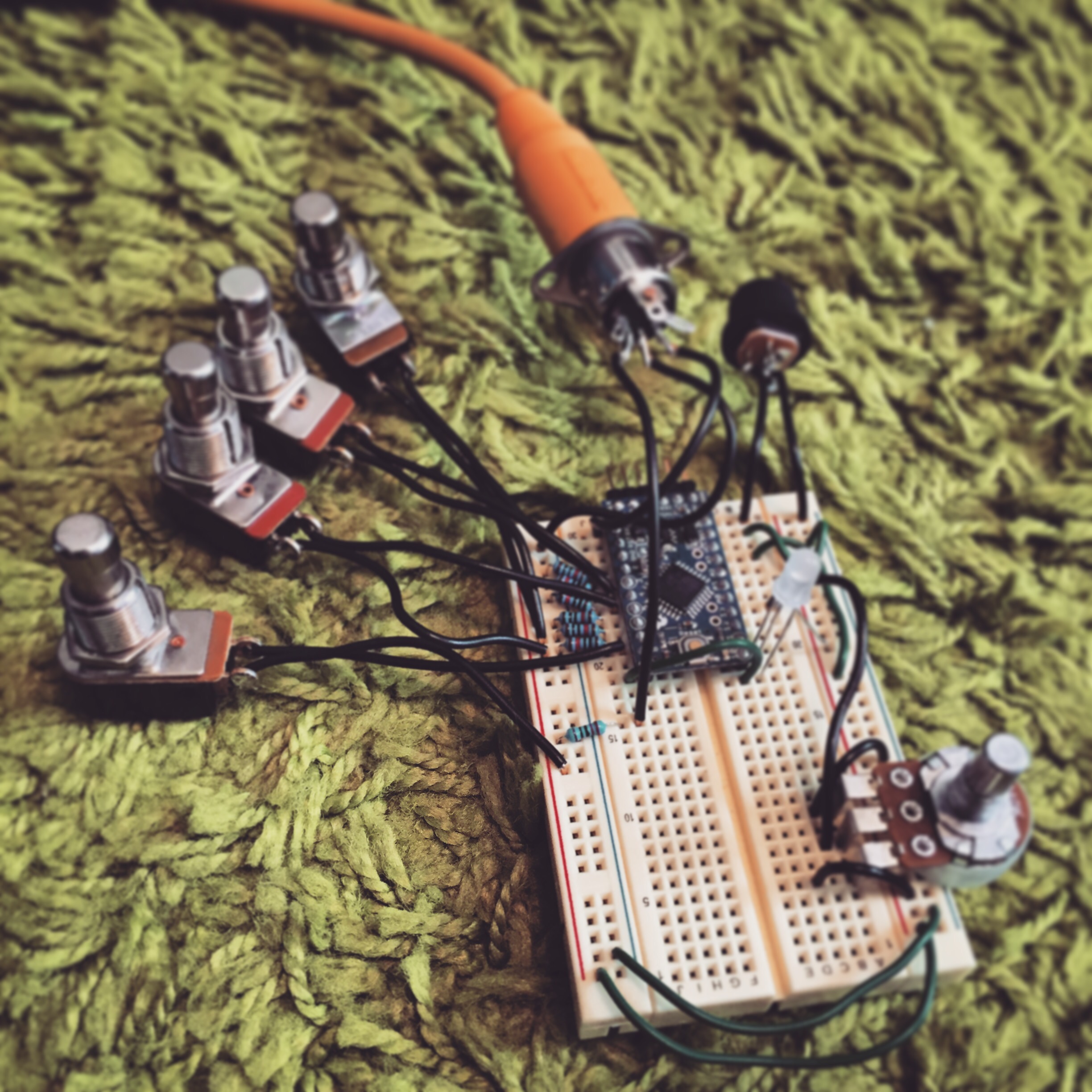
Introducing the Controleon prototype

(null)

Objective:
This project is finally taking some shape over this 3 day weekend we just had. My goal with this project was to make an easy to use and functional MIDI foot controller to use with my Strymon pedals and Logic Pro transport controls. Since I wanted to only use 6 momentary switches for this project, I will need a type of layering system for multiple functions. Most MIDI foot controllers on the market are expensive & very complicated since they want to jam as much functions in as possible. I wanted something more personalized to me and my board.

Hurdles:
I have never built anything like this with a Arduino before and there was a learning curve but I moved along pretty quickly. I spent a lot of time (got hung up) in the design phase and had to scale it back some and told myself that this project can always grow. Start small and end big.

Hardware used:

Arduino Pro Mini (5V and 16 MHz)

  • Has a very small footprint. 0.7″ x 1.3″
  • It is based on the ATmega168 chip
  • 14 digital input/output pins & 8 analog inputs.
  • Operates on 5v-12v DC.

FTDI Basic from SparkFun

  • This is used for programming the Arduino Pro Mini VIA USB.

Arduino Libraries Used:

  • Arduino MIDI Library – All basic MIDI CC and PC covered with this library
  • ClickButton – Used for single click, double click or click and hold functions.
  • Bounce2 – This is used to de-bounce switches for more accurate readings.

 Layers:

The concept was to have 6 buttons and have one button control what “mode” you were in. I currently made 4 layers so that gives me 20 buttons for functions. I could also make the 6th button (mode select button) a “click and hold” to change modes and use it as a regular select button when clicked (May work on this more later). I have a RGB LED that has a color for each layer so you don’t get lost on what layer you are on.

Example of the RGB LED for modes:

https://www.youtube.com/watch?v=WxMpMBMC-9w

Information Used:

Once I am done with the proto PCB I will post all the code and PCB here.

Screw dimensions for different guitar parts

Info posted by cooterfinger from shortscale.org

Sheet metal screws:

Fender hardtail bridges, strap buttons
#6 thread, 1” length oval head Phillips, stainless, sheet metal
Fender control plates and pickguards
#4 thread, ½” length, oval head phillips, stainless, sheet metal
Fender tuners
#2 thread, 3/8” length, round head Phillips, stainless, sheet metal
Fender string tree
#2 thread, 5/8” length, round head Phillips, stainless, sheet metal
Fender neck plate
#8 thread, 1 ¾” length, oval head Phillips, stainless, sheet metal

Machine screws:

Fender switch mounting screws
6-32 thread, 3/8” length, round or pan head Phillips, stainless, machine
Fender telecaster bridge pickup mounting screws
6-32 thread, 5/8” length, round or pan head Phillips, stainless, machine

Misc:
Bronco trem collar
Chrome 3/8”-24 Jam Nut
Bronco spring retainer
Stainless Steel 8/32”-1 ¼” O.H. machine
Gibson pickguard screws
Stainless steel 3/8”
Humbucker mounting ring screws
9/16” Phillips flathead
Humbucker height screws
3-48 thread 1 ¼” length
Single coil height screws
6-32 thread, 11/16” length Phillips ovalhead
Tele neck pickup
1 1/16” Phillips roundhead wood screw

Aria, japanese type jag bridge screws are:
#4-40 x 3/8″ Phillips Oval Head Machine Screw 18-8 Stainless Steel (72732 fastenal)
#4-40 x 3/4″ Phillips Round Head Machine Screw 18-8 Stainless Steel (fastenal 72489)

Dirtbaby Delay

This is Madbean’s Dirtbaby delay. It is his take on a PT2399 based delay that has some of the same qualities of the BBD Electro-Harmonix Deluxe Memory Man. This is by no means a “Clone” of the Deluxe Memory Man but a great sounding PT2399 based delay. This is by far my favorite sounding PT based delays that I have built and the 2nd runner up is a 1776 Effects Multiplex (They really are 2 different beasts since the multiplex is a great tape emulation). It really is the modulation that sells this for me as it sounds so lush and adds a whole other dimension to the delays.

The artwork may be familiar since it was used on another pedal I did a year ago but I loved it so much I really wanted to do a pedal that would be a staple on my board with it. The original artwork is from a bands cover art that I found on Google Images. I did a reverse etch and painted it with the Rust-Oleum 7250830 Metallic Spray and used a Dupli-Color clear coat.
The knobs I used are silver aluminum knobs from Eagle Plastic Devices bought from Mouser. Eagle Plastic Devices make some great plastic & aluminum knobs.

Box Shot:
(null)

Gut Shot:
(null)

The 3PDT breakout board was made by me in Diptrace and is available here if you wish to etch it for yourself. It really helps to keep your switch install clean.
Dirtbaby 3PDT

Pennyroyal Chorus

The Pennyroyal Chorus is a PCB made by Stomptown Electronics and is a MN3007 based chorus. From lushy subtle to super seasick warbly, this pedal has it all. With a plate reverb and a few repeats from a delay you can nail some great Cocteau Twins songs and a long list of 80’s songs. I needed a good analog chorus on my board and this build definitely fit the bill.

I did a reverse etch of a three eyed cat (Google Images swipe), why? (enter witty comment here) I painted the enclosure with a root beer sparkle brown found at a hobby store. I shot it with some gloss clear and called it done.

Box Shot:
IMG_0153.JPG

Gut Shot:
IMG_0154.JPG

I would definitely recommend this build to anyone that wants a great sounding analog chorus. It doesn’t have all the bells and whistles as the newer digital ones but it simplicity and its sounds is what sets it apart.

Buy a PCB here.

Rullywow’s Griddlecake

IMG_0149.JPG

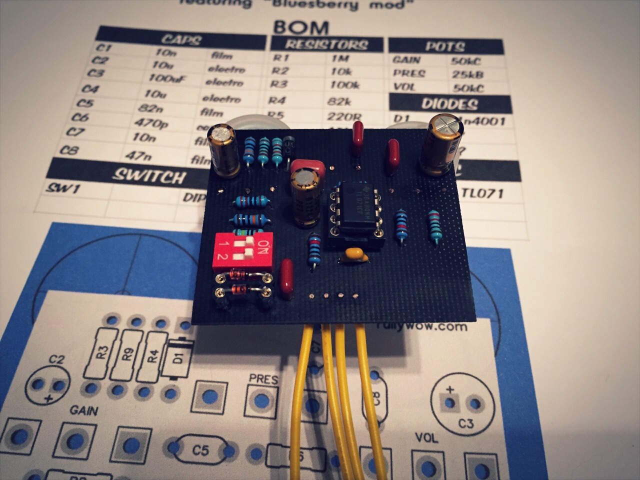
This was a quick little build on Rullywow‘s new single sided layout based on the Crowther Audio Hotcake with the “Bluesberry” mod. You can find this layout on Madbeans Forums. There is a lot of talk whether or not the Bluesberry mod actually does anything. The Crowther Audio Hotcake is known for the fizzy note decay on most super clean (Fender Twin) amps. There are a lot of VOX amp fans that swear by this OD and it works so well with a already dirty clean tone. The fizzyness is less noticeable on a already broken up or on the edge of breaking up amp. The Bluesberry mod does NOT remove the fizzy note decay, but it smooths out the tail of it a bit and makes it manageable in my opinion. I was able to crank up my Fender Princeton Reverb custom and it sounded absolutely fantastic. This will be boxed up for sure.

Build Doc

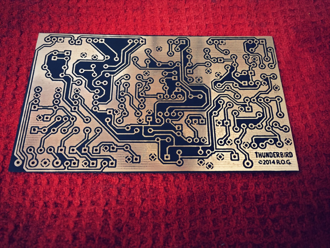
1776 Effects Thunderbird Etch

thunderbird_PCB

This is the new ROG Thunderbird laid out by Josh at 1776 Effects. In the build doc was included an etchable layout. There is also a fabricated PCB version of this available.

Capturing the majestic sound of a Marshall Super Lead amplifier.

This was by far the most complex PCB etch I have done due to the small and close traces. I just took my time with the etch mask and it seemed to have come out great. I will do a continuity test to make sure I do not have any shorts.

Back to the bench!

How the trimpots have to be set up in BBD-based circuits

This was taken from user Jenz over at DIYStompboxes

Since i have read many posts about squealing EH MemoryMan’s and Electric Mistress’, i decided to give some info (even for beginners) on how the trimpots have to be set up in BBD-based circuits. I know, not all circuits offer the possibilities to adjust EVERY aspect of the BBD, but this should only be a guide to get the best out of them and what to look for
To tell you the things to be done, check out the Deluxe ElectricMistress schematic at Luckily, this circuit has 5 trimpots for all adjustments as seen on the Memory Man as well.
Be sure you have a scope and a sine-wave low-frequency generator since this will give the best results…
Here we go:

Step 1: BBD balance
settings: Feedback, Rate, Range & Levels to CCW
This is a scope job if you want best results…
Connect the scope tip to the taper of the 1K ‘BAL. ADJ.’ pot that is connected between pin 6 & pin 12 (outputs) of the SAD1024 and adjust for minimum bleed-through of the clock signal. You can’t adjust this to ‘ideal zero’, so the best is a setting which shows both clock-wave components at equal minimum level. The ideal balance setting varies with delay time, so maybe re-adjust for best results over the entire delay time range.

Step 2: BBD offset/bias
settings: Feedback, Rate, Range & Levels to CCW
This is a scope job if you want best results, but could be done by ear, too. This is an important setting since it determines the maximum undistorted output level of the BBD.
Connect scope tip to taper of the 1K ‘BAL ADJ.’ pot. Feed 400Hz sinewave into input. Increase output level of generator until the signal shows clipping. Adjust the 10K ‘BIAS ADJ.’ pot for symetrical clipping / proper sine wave. IMPORTANT:
Most BBD- based circuits have a pre-emphasis network in front and a de-emphasis network behind the BBD. This means, treble is boosted in front of the BBD and cut down the same amound behind the BBD to keep BBD-noise level low. This maybe affect the ideal offset setting. For best offset setting, check the adjustment of the 10K ‘BIAS ADJ.’ pot with different input frequencies! The ideal offset setting varies with delay time, so maybe re-adjust for best results over the entire delay time range. BBD offset and BBD balance interact a little with each other, so check back!

Step 3: BBD gain
setting: Feedback, Rates, Range & CCW, Delay Level to MAX
This could be done by scope or by ear. This setting sets the level of the delayed signal in relation to the dry signal. This could be adjusted to taste, but the most common setting is to have equal volumes on delayed and dry signal. On short delay times (as on flangers) there’s a scope trick to achieve equal volumes: Connect scope tip to pin 7 of the 4558 (right of the SAD1024). (REMEMBER: Don’t connect to the taper of the 1K ‘BAL. ADJ.’ pot this time, because we need to cancel out the effects of the pre/de-emphasis network this time!) Feed 400Hz sinewave into input. If you now change the delay time knob, you can see the sinewave going up an down in volume as long as you turn the knob. Because you vary the delay time, there are boosts and cuts at certain frequencies due to phase cancelations. Adjust the delay time knob to a position where a maximum cut/cancelation occurs. Now adjust the 10K ‘GAIN ADJ.’ pot for zero output. Now, delayed and dry signal are in equal volume, because the sine wave is fully canceled. This adjustment interacts with the ‘BBD balance’ setting, so maybe you have to re-adjust it after setting BBD gain. Due to the tolerances of the resistors and caps in the pre/de-emphasis networks, the ideal gain setting should be re-adjusted with differnt input frequencies. Delay time setting affects this adjustment too, so check back with different settings or just adjust to taste

Step 4: BBD clock
setting: Feedback, Rates, Range & CCW
This is mostly an uncritical setting, since it just determines the minimum/maximum delay time covered by the delay time knob. This pot affects the clock circuit that drives the BBD. On the schematic, it’s the unnamed 100K trimpot connected to Ub and the 3k9 resistor left of the CD4013. Only on long delays, this setting might be critical. If the clock frequency is adjusted too low (high clock frequency = short delay time, low clock frequency=long delay time), the clock signal might come down to audio range and will be heard as ‘faint’ signal. So adjust this trimpot until no clock is heard or adjust to taste and get some weird sounds

Step 5: FEEDBACK
setting: Feedback to MAX, Rate to CCW, Range to MAX
This is no direct BBD-related adjustment, but is found on most delays, flangers and phasers.
This trimpot (the 100K ‘F.B. TRIM’) limits the range of the Feedback knob. While feedback knob in MAX position, adjust for maximum possible feedback with no self-oscillation. Re-adjust with different delay times, some circuits intend to get into self-oscillation at shorter delay times….or adjust to taste for driving the circuit into self-oscillation for wild feedback.

I think that’s it

regards, Jens

Gigahearts FX Doubel Ganger

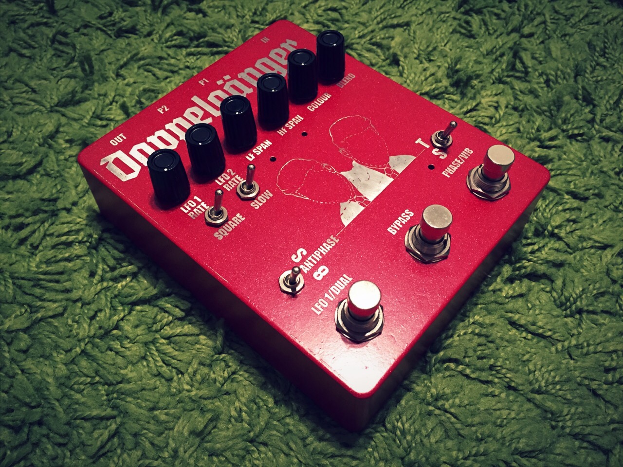
This is an effect based on the Lovetone DoppelGanger the twin oscillator phaser/vibrato. This thing can nail that classic phaser sound of the 70’s to out of this world stuttering and blipping. This is by no means just a “noise maker”, It is very usable and very easy to control. I got the PCB little over 9 months ago from LaceSensor at Madbean forums.

There is a 2015 PCB group buy going on right now.

I did a reverse etch and used some simple but effective artwork I wound on Google images. The enclosure is a 1790NS.
IMG_0134.JPG

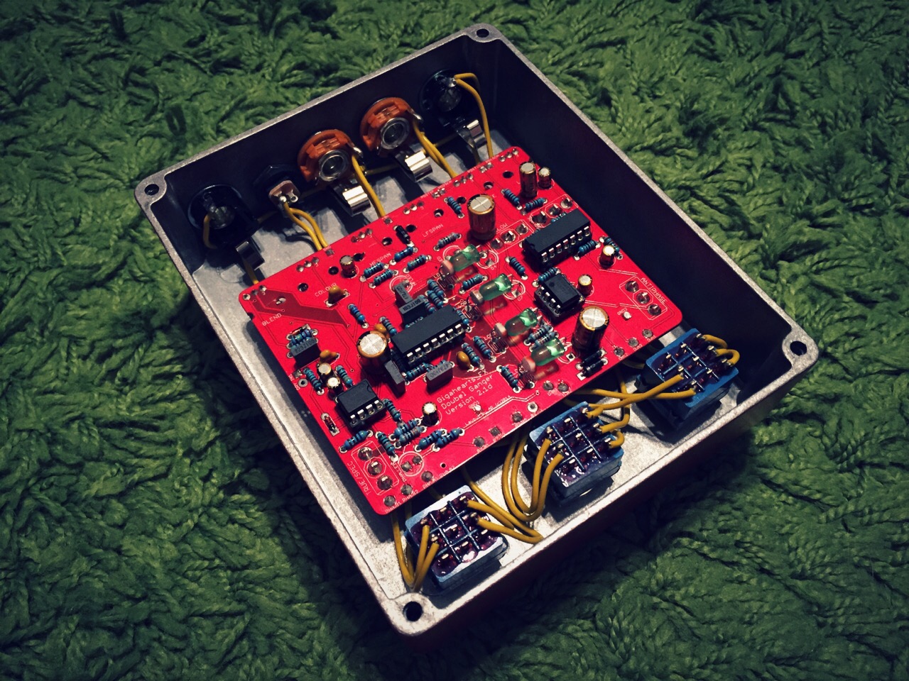
Gut shot: Built to spec with no subs.
IMG_0133.JPG

Notes:
I used GL5537 LDRs that I bought from MKLec