Category: Good to Know

Shruthi XT Journey

This is not really a step-by-step tutorial, its more of a “point you in the right direction” tutorial. I just made notes as I was getting my Shruthi XT working. Most of the command line AVRDUDE stuff was found all over the web, I just wanted to archive what worked for me.

For Windows 10 Disable Driver Signature Enforcement: VIDEO
Unzip THESE FILES to root of C:/
Plug in your USB AVRISP XPII/MXII (Default drivers might fail, this is fine, ignore for now)
Install C:\shruthi\Software\libusb-win32-bin-1.2.6.0\bin\inf-wizard.exe
Install C:\shruthi\Software\WinAVR-20100110-install.exe
Open a command window (Press Win+R and type cmd and hit enter)
type cd C:\shruthi\ (You should now be in the C:\shruthi\ directory)

Type:

avrdude -p m644p -c avrispmkii -P usb -v

The RED light on the AVRISP XPII/MXII should have turned GREEN and you should see “avrdude done. Thank you.” in the command windows.
If this is true, then continue to the next step. If the light is still RED then remove your drivers and try again.

Hook up the 6 PIN cable from the AVRISP to the AVRISP port on the Shruthi XT.

Power up the Shruthi XT

Were going to set the fuses first. Type the following and hit enter:

avrdude -B 100 -V -p m644p -c avrispmkii -P usb -e -U lock:w:0x3F:m -e -u -U efuse:w:0xFD:m -U hfuse:w:0xD6:m -U lfuse:w:0xFF:m -U lock:w:0x0f:m

Now were going to program the bootloader and OS. Type the following and hit enter:

avrdude -B 1 -V -p m644p -c avrispmkii -P usb -U flash:w:shruthi.hex:i -Uflash:w:muboot.hex:i -U lock:w:0x2f:m

This will program the first 16 presets. Type the following and hit enter:

avrdude -V -p m644p -c avrispmkii -P usb -U eeprom:w:internal_eeprom.hex:i

Power off the shruthi XT and remove the 6 PIN cable from the programmer
Press the encoder knob in and insert the power cable and select XT.
Enjoy

Enclosure Etch Woes

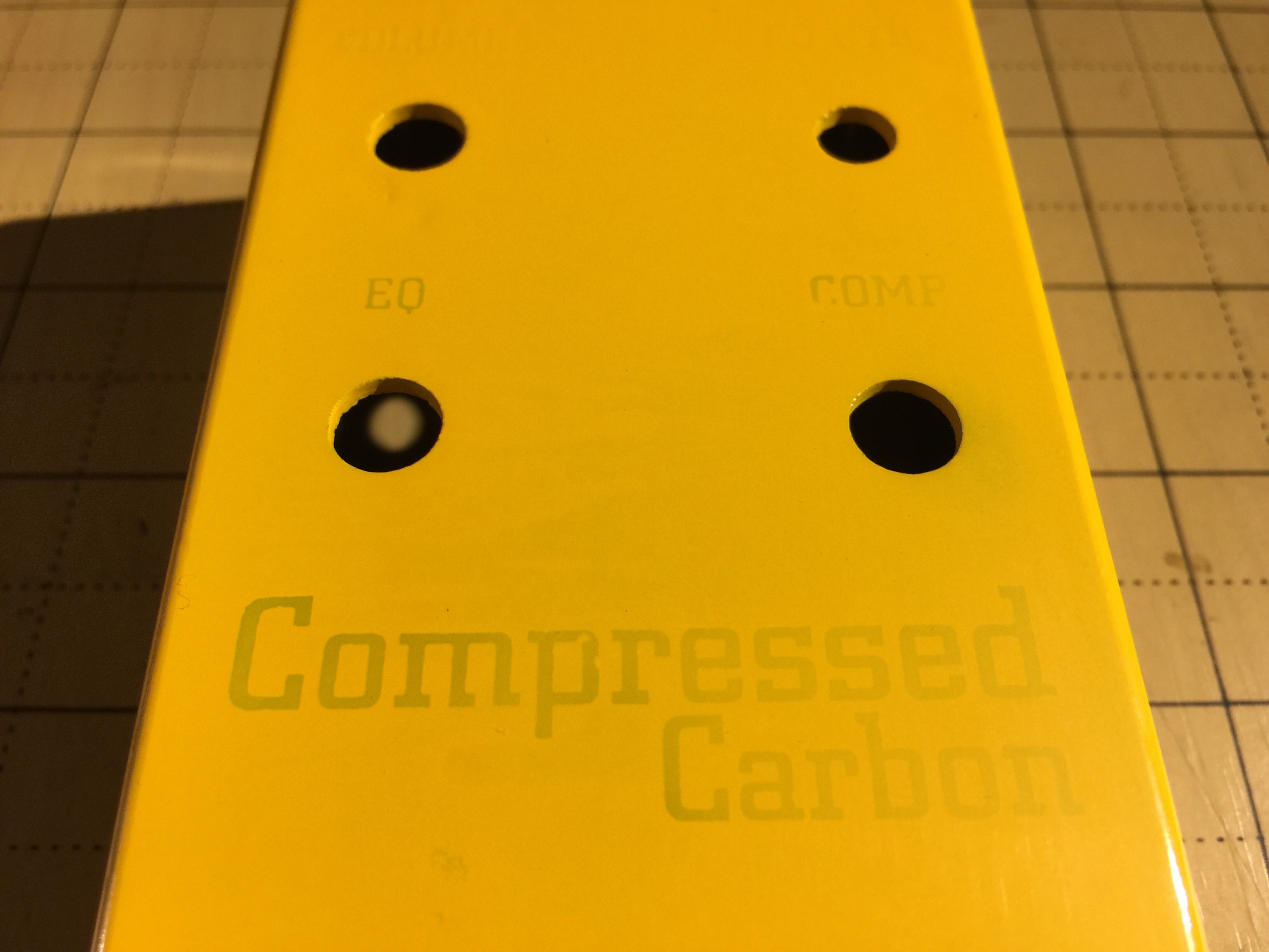
Here’s an example of a bad reverse etch. This is a perfect example of me trying to use a paint that is too thick/super glossy on a reverse etched enclosure.

What your looking at is a enclosure I reverse etched the text on and painted with a Krylon glossy yellow. I then tried to wet sand the top to expose the raised areas, the only problem is, there is no longer any raised areas. The paint filled in/up all raised areas making it impossible for me to sand away the paint to expose the aluminum.

So how do you know what paints work well for etching?

I have come to the conclusion that flat colors work the best. I am able to do a few thin layers and then oven dry it then wet sand to expose the etch. I then shoot the enclosure with a nice clear coat and call it done.


Cutting CEM (Composite epoxy material)

I have been sitting on a bunch of 4″x6″ CEM (Composite epoxy material) that I got from a copper clad vendor online. I thought it would be cool to use for prototypes since the board is kind of ugly looking. When I first got it I found that the thickness was giving me some issues with cutting it like I do with my copper clad laminate. I tried with my chop paper cutter and it almost broke it. I also tried a jig saw and the blade would gum up and start melting the board. The Dremel took forever to cut it and it would also gum up the blades. I was about to give up when I ran across some plastic cutting blades for my scroll saw. I used Ryobi skip tooth 18.5 TPI blades and it cuts it like butter. I am excited that I can start using this clad for future projects.

Just thought I would share my trials & errors.

Screw dimensions for different guitar parts

Info posted by cooterfinger from shortscale.org

Sheet metal screws:

Fender hardtail bridges, strap buttons
#6 thread, 1” length oval head Phillips, stainless, sheet metal
Fender control plates and pickguards
#4 thread, ½” length, oval head phillips, stainless, sheet metal
Fender tuners
#2 thread, 3/8” length, round head Phillips, stainless, sheet metal
Fender string tree
#2 thread, 5/8” length, round head Phillips, stainless, sheet metal
Fender neck plate
#8 thread, 1 ¾” length, oval head Phillips, stainless, sheet metal

Machine screws:

Fender switch mounting screws
6-32 thread, 3/8” length, round or pan head Phillips, stainless, machine
Fender telecaster bridge pickup mounting screws
6-32 thread, 5/8” length, round or pan head Phillips, stainless, machine

Misc:
Bronco trem collar
Chrome 3/8”-24 Jam Nut
Bronco spring retainer
Stainless Steel 8/32”-1 ¼” O.H. machine
Gibson pickguard screws
Stainless steel 3/8”
Humbucker mounting ring screws
9/16” Phillips flathead
Humbucker height screws
3-48 thread 1 ¼” length
Single coil height screws
6-32 thread, 11/16” length Phillips ovalhead
Tele neck pickup
1 1/16” Phillips roundhead wood screw

Aria, japanese type jag bridge screws are:
#4-40 x 3/8″ Phillips Oval Head Machine Screw 18-8 Stainless Steel (72732 fastenal)
#4-40 x 3/4″ Phillips Round Head Machine Screw 18-8 Stainless Steel (fastenal 72489)

How the trimpots have to be set up in BBD-based circuits

This was taken from user Jenz over at DIYStompboxes

Since i have read many posts about squealing EH MemoryMan’s and Electric Mistress’, i decided to give some info (even for beginners) on how the trimpots have to be set up in BBD-based circuits. I know, not all circuits offer the possibilities to adjust EVERY aspect of the BBD, but this should only be a guide to get the best out of them and what to look for
To tell you the things to be done, check out the Deluxe ElectricMistress schematic at Luckily, this circuit has 5 trimpots for all adjustments as seen on the Memory Man as well.
Be sure you have a scope and a sine-wave low-frequency generator since this will give the best results…
Here we go:

Step 1: BBD balance
settings: Feedback, Rate, Range & Levels to CCW
This is a scope job if you want best results…
Connect the scope tip to the taper of the 1K ‘BAL. ADJ.’ pot that is connected between pin 6 & pin 12 (outputs) of the SAD1024 and adjust for minimum bleed-through of the clock signal. You can’t adjust this to ‘ideal zero’, so the best is a setting which shows both clock-wave components at equal minimum level. The ideal balance setting varies with delay time, so maybe re-adjust for best results over the entire delay time range.

Step 2: BBD offset/bias
settings: Feedback, Rate, Range & Levels to CCW
This is a scope job if you want best results, but could be done by ear, too. This is an important setting since it determines the maximum undistorted output level of the BBD.
Connect scope tip to taper of the 1K ‘BAL ADJ.’ pot. Feed 400Hz sinewave into input. Increase output level of generator until the signal shows clipping. Adjust the 10K ‘BIAS ADJ.’ pot for symetrical clipping / proper sine wave. IMPORTANT:
Most BBD- based circuits have a pre-emphasis network in front and a de-emphasis network behind the BBD. This means, treble is boosted in front of the BBD and cut down the same amound behind the BBD to keep BBD-noise level low. This maybe affect the ideal offset setting. For best offset setting, check the adjustment of the 10K ‘BIAS ADJ.’ pot with different input frequencies! The ideal offset setting varies with delay time, so maybe re-adjust for best results over the entire delay time range. BBD offset and BBD balance interact a little with each other, so check back!

Step 3: BBD gain
setting: Feedback, Rates, Range & CCW, Delay Level to MAX
This could be done by scope or by ear. This setting sets the level of the delayed signal in relation to the dry signal. This could be adjusted to taste, but the most common setting is to have equal volumes on delayed and dry signal. On short delay times (as on flangers) there’s a scope trick to achieve equal volumes: Connect scope tip to pin 7 of the 4558 (right of the SAD1024). (REMEMBER: Don’t connect to the taper of the 1K ‘BAL. ADJ.’ pot this time, because we need to cancel out the effects of the pre/de-emphasis network this time!) Feed 400Hz sinewave into input. If you now change the delay time knob, you can see the sinewave going up an down in volume as long as you turn the knob. Because you vary the delay time, there are boosts and cuts at certain frequencies due to phase cancelations. Adjust the delay time knob to a position where a maximum cut/cancelation occurs. Now adjust the 10K ‘GAIN ADJ.’ pot for zero output. Now, delayed and dry signal are in equal volume, because the sine wave is fully canceled. This adjustment interacts with the ‘BBD balance’ setting, so maybe you have to re-adjust it after setting BBD gain. Due to the tolerances of the resistors and caps in the pre/de-emphasis networks, the ideal gain setting should be re-adjusted with differnt input frequencies. Delay time setting affects this adjustment too, so check back with different settings or just adjust to taste

Step 4: BBD clock
setting: Feedback, Rates, Range & CCW
This is mostly an uncritical setting, since it just determines the minimum/maximum delay time covered by the delay time knob. This pot affects the clock circuit that drives the BBD. On the schematic, it’s the unnamed 100K trimpot connected to Ub and the 3k9 resistor left of the CD4013. Only on long delays, this setting might be critical. If the clock frequency is adjusted too low (high clock frequency = short delay time, low clock frequency=long delay time), the clock signal might come down to audio range and will be heard as ‘faint’ signal. So adjust this trimpot until no clock is heard or adjust to taste and get some weird sounds

Step 5: FEEDBACK
setting: Feedback to MAX, Rate to CCW, Range to MAX
This is no direct BBD-related adjustment, but is found on most delays, flangers and phasers.
This trimpot (the 100K ‘F.B. TRIM’) limits the range of the Feedback knob. While feedback knob in MAX position, adjust for maximum possible feedback with no self-oscillation. Re-adjust with different delay times, some circuits intend to get into self-oscillation at shorter delay times….or adjust to taste for driving the circuit into self-oscillation for wild feedback.

I think that’s it

regards, Jens

PIC Programming

11-8-2015 Update:

With OS X 10.11 El Capitan incorporating SIP (System Integrity Protection) it will break your previous install of PicKit2GUI. You will need to disable SIP before you can copy the needed files into the /bin/ directory to get PicKit2GUI to work again.

I found I also needed to install Java for OS X 2015-001 package first to get the JAVA runtime installed on OS X 10.11

Reboot your Mac into Recovery Mode by restarting your machine and holding down Command + R until you see the Apple logo. Then click Utilities > Terminal

In terminal window type the command: csrutil disable

Restart you Mac and SIP will be disabled. You are now able to re-copy over the pk2cmd and PK2DeviceFile.dat to the /bin/ directory.

Don’t forget to run: sudo chmod 777 /bin/PK2DeviceFile.dat


Recently I programmed 50 PIC16F684 chips to use ElectricDruid’s TAPLFO program. I have been asked by a few people how I burned the chips and with what. I decided the best thing to do was make a quick walk through.

Since I did all this on my Macbook Pro, this tutorial will be geared towards a Mac but the concept is the same with a PC.

Why did I need/want these chips?

There have been some great pedal DIY projects that use this chip to tap in a temp from a foot switch. Here is a small list of projects that use this chip and I am sure there are many more.

What I needed/what I had on hand?

PIC Chip – You will need a PIC16F684 You can pick them up at Mouser or try your luck with some China ones on eBay.

USB Programmer – There are so many programmers out there that it is impossible to cover them all. This is usually the biggest stumbling block when getting started. I went with the CanaKit UK1300 USB PIC Programmer (PicKit2 Clone) since it also meet my needs at work. I really like the fact that the sockets are on board and I do not need any accessories for it to program out of box.

Software – I really wanted to use MPLABX on my Mac but I had nothing but troubles trying to get it to recognize the CanaKit UK1300 so I went with using pk2cmd. When searching for command switches pk2cmd I came across a really nice Java GUI called PicKit2-Programmer-GUI that worked perfectly.

TAPLFO ProgramElectricDruid has this available on his website for private use only. If you like to use it commercially please contract Tom Wiltshire. Dpwnload the Assembled HEX code here.

My Programmer:
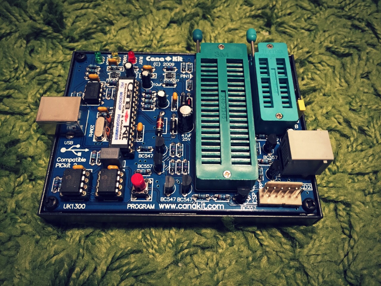
pickit2To write the TAPLFO program to the chip do the following:

Hook up your programmer VIA USB. You should have some kind of status light on your programmer to let you know it is powered up.

Insert your PIC (PIC16F684 in this case) – This step can be done before or after the software is launched. I am asking for you to do it before we launch so you can see if PicKit2GUI detects the chip properly.

Launch the PicKit2GUI
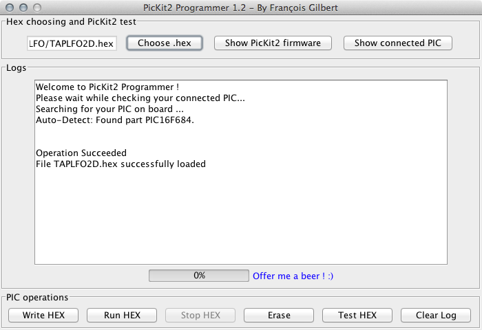
PivKit2cmdgui

As you can see from the picture above the software detected that I have a PIC16F684 inserted (Auto-Detect: Found Part PIC16F684)

Load up the TAPLFO.hex file downloaded from Electric Druid into the PicKit2GUI software by pressing the “Choose .hex” button

I always erase my PIC before any programing. I think its just a “best practice” and is most likely not necessary.

Erase:
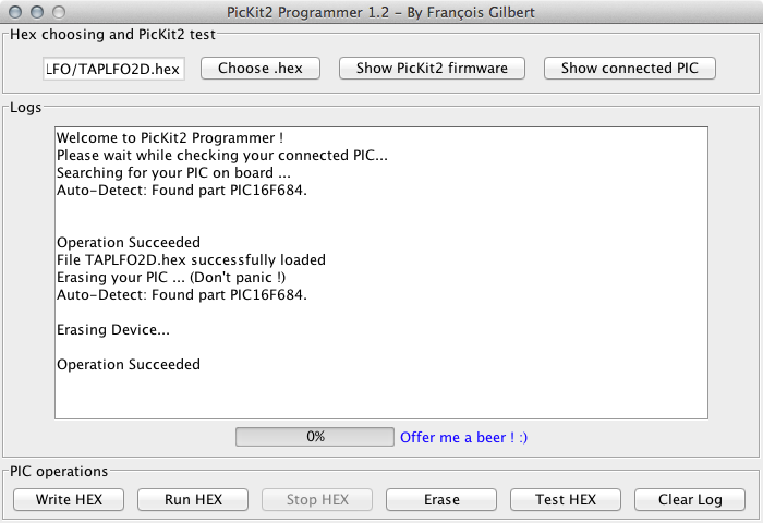
pickit2guierase

Write:

Now lets write the HEX file to the PIC16F684. Press the “Write Hex” button.
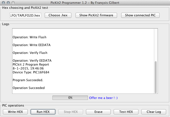
pickit2guiwriteTest Hex:

Another good practice is to test the HEX on the PIC to verify a working chip. Press the “Test HEX” button.
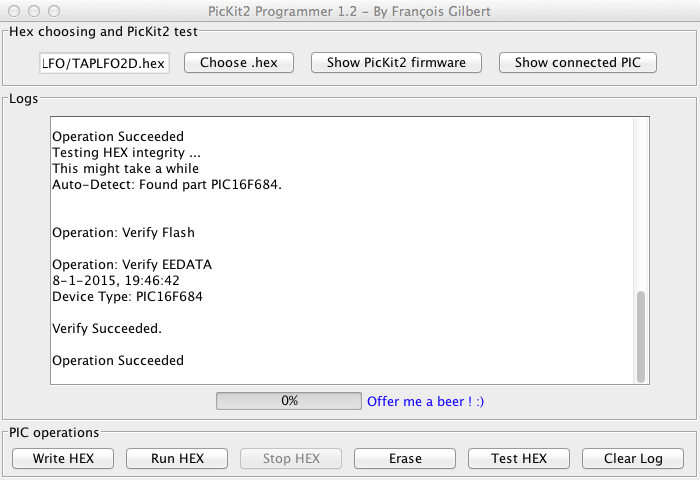
pickit2guiverify

Now were are done. Just remove the PIC16F684 and place another in its place if you want to program more chips. There is no need to shut down the software or power off the programmer when changing the chips.

Now you can make some snazzy labels for your chips and get using them in your personal DIY projects.

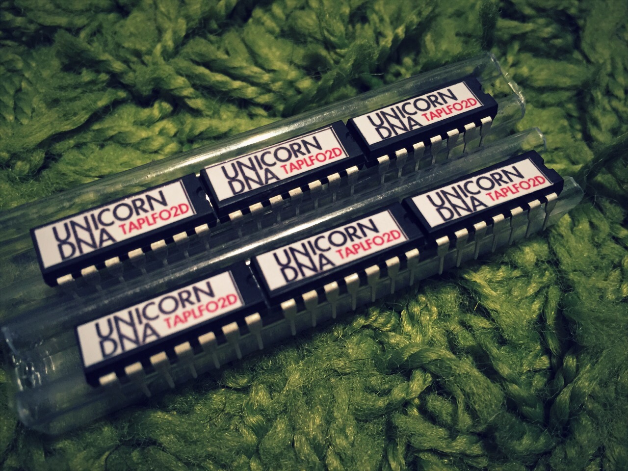
Sticker Sizes: 16.34mm X 5mm 300DPI worked perfect for me. Print them on a full sheet of sticker paper and just cut them out as needed.

Here is a shot of some of my finished chips.
IMG_0070.JPG


Enclosure Painting Tutorial

I finally got a tutorial together on how I paint and wet sand my enclosure after I do a reverse etch. I will be making changes to it over time since my process is evolving with every project. My goal is to get consistent results and little room for error. As with everything with this blog, if you have questions or comments please feel free to express them. I am also always open for more ides or suggestions.

Enclosure Painting Tutorial

Great Fuzz Face Transistor Info

Ran across this blurb and wanted to archive it. This is taken from Mac at DIYSB

Rule of thumb, as long as the you match the right hfe for a fuzz it will sound good.

q1: hfe=70-90, leakage <50ua better but can be up to 200uA
q2: hfe=90-120, leakage <200ua but 300-400 may work.

q1 should be low leakage so as to have 4.5v at q2 collector with a resistor closer to the original 8.2k.
Also q1 has a much great effect on the bias resistors than q2. Just finger heat the transistors one at a time and watch what happens at q2 collector. Or if you bias the circuit with 4.5v at q2 collector, and you replace q2 with a leaky transistor ot much higher gain, vc2 will move a little. Put the original q2 and replace q1; vc2 will jump a lot.

About the sound, I have some american and japanese transistors with the right parameters, ie, the ones above. I know some may say I’m crazy but there are differences. Some are brighter, some darker, some have more mids, etc. But they all have fuzz nicely.

Stratocaster Tone of the Stars

Saw this posted on TGP and found it funny to see how he summed up the pickup selection switch. All in all it is a nice tidbit of info but there are many factors involved in the musicians mentioned below to make this accurate in my opinion. So think of this info as a “just for fun” kind of info.

– neck = Jimi, Hank Marvin
– neck + mid = SRV, John Mayer
– middle = Rory Gallagher
– middle + bridge = Mark Knopfler 
– bridge = David Gilmour, Ritchie Blackmore, Jeff Beck, Hank Marvin, Eric Johnson…