Making Arrangements (Direction)
Affectronix The Pink Verb
The people over at FSB are working on a layout for the Affectronix The Pink Verb and I thought I would take a stab at it. I found some pictures from the maker and decided to trace his PCB with in Sprint-Layout.
Info about the Pink Verb
The Pink Verb is a tube style, analog reverb and tube overdrive pedal. It uses one preamp tube (12AX7/ECC83) instead of those complicated Fender tube reverbs which use 3 tubes and a transformer. This pedal gets right to the point of what it’s intended to do.
If you didn’t know, most reverb pedals are digital, but this one is analog which makes it sound natural. Digital reverbs use digital programmed chips to model the sound that reverb tanks make. Analog reverbs, like The Pink Verb, use reverb tanks to create a natural and real sounding reverb. For those of you who don’t know what a reverb tank is, it is a larger component with 2-3+ springs with a transducer on either side. When your guitar is played through one, the springs vibrate and create a sort-of echo sound to fill out the tone. But, the reverb tank must be driven and recovered to keep up the volume and to have sound.
Here is what I got so far.
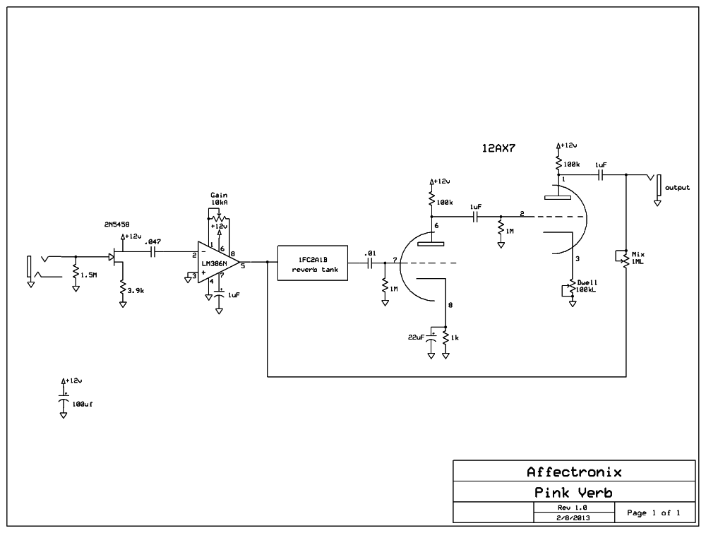
Here are the schematics by a FSB member.
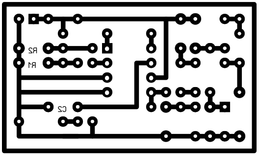
This is the photo that was released by the maker.
 I cropped and flipped the image in Adobe Photoshop.
 Next I take it in to Sprint-Layout and trace it out. Here is the transfer at 600 DPI
Now I just need to figure out the layout. I am bad at this and just need more practice reading schematics.
BOM:
R1 1.5M
R2 3.9K
R3 1M
R4 1K
R5 100K
R6 1M
R7 100K
C1 47nF
C2 1uF
C3 10nF
C4 22uF
C5 1uF
C6 1uF
Q1 2N5458
GAIN 10KA
DWELL 100KL
MIX 1ML
OP LM386M
Reverb Unit 1FC2A1B
Tube 12AX7/ECC83
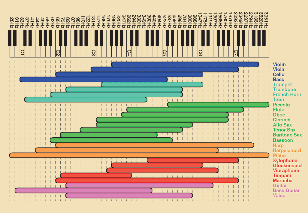
Great chart of frequencies
Tayda coupon code
No Money… No Parts…
For All My Switches
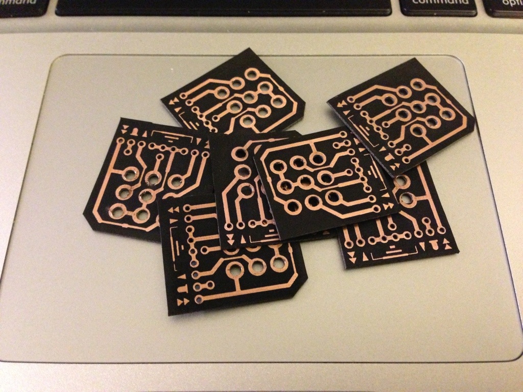
Tired of wiring switches? I definitely am so made these to help smooth out out the process.
I found the pcb transfer on a Google cache page and have no idea how came up with the original layout of these. I am by no mean taking credit for designing them. I converted the JPEG to PDF.
Update: Now that I have used a couple of them I think I want to add a +9v lead on it for the LED. Other than that, I am really happy with them.
Pink Muff
Electro-Harmonix Big Muff Pi (Violet Rams Head)
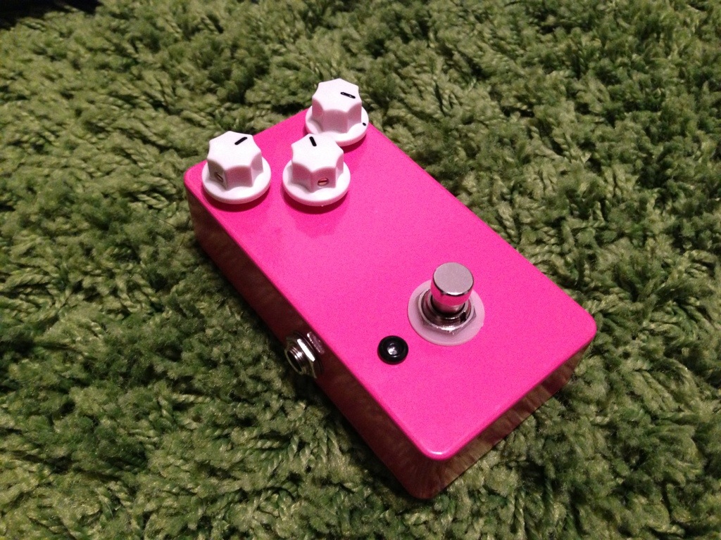
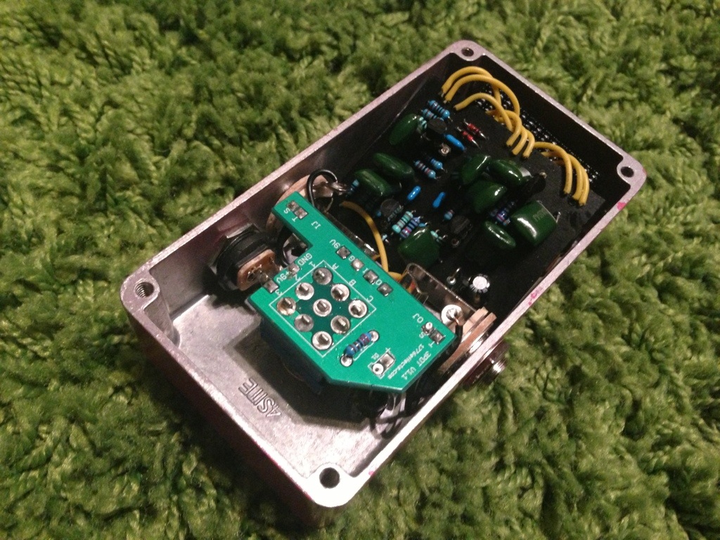
I made this from the MadBean Mudbunny layout. I etched the transfer on a black laminent copper clad board. I am really happy how it came out. I think it sounds better than my 90’s NYC muff and it has a smaller footprint which is a plus.
Sound Samples:
[soundcloud]https://soundcloud.com/selfdestroyer/bmp2/s-CISCr[/soundcloud]
And now for my ghetto rendition of a Smashing Pumpkins song.. everything is wrong about it but you get the idea.
[soundcloud]https://soundcloud.com/selfdestroyer/bmp1/s-mNWMh[/soundcloud]
Mid-fi clari(not) clone
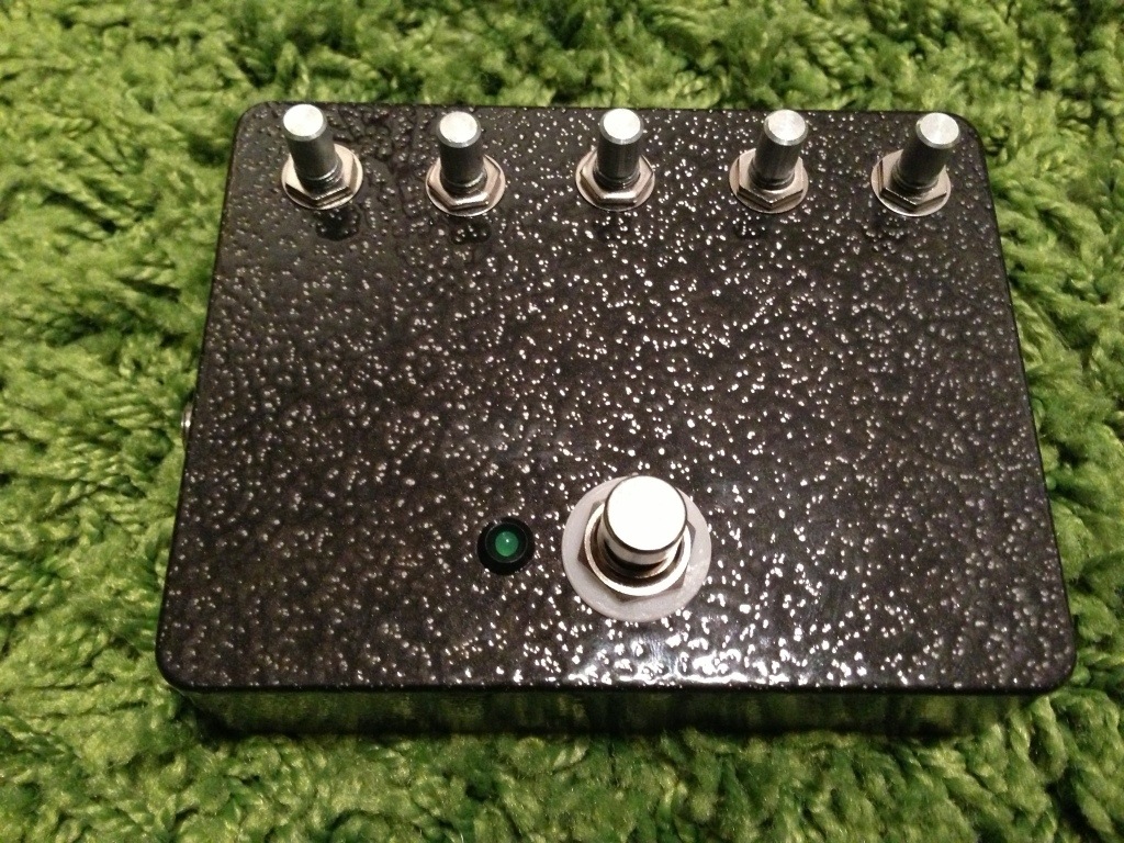
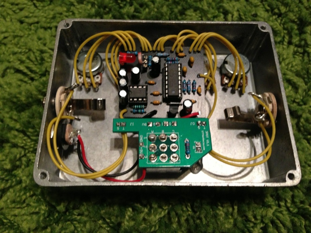
I was wanting a modulating fuzz like using a tremolo bar and I stumbled on to the Mid-Fi Clari(not) pedal. Some really unique sounds are produced with this pedal and I wanted to see if I can clone it. To my surprise a member of Madbean forums did a layout for it. I etched a PCB and went to work. Here is the outcome. I am waiting for the knobs i ordered and I will be using rubber stamps for the controls.
Sound Samples: (Logic Pro / Amp Designer with some reverb)
[soundcloud]https://soundcloud.com/selfdestroyer/carinot1/s-QWbP3[/soundcloud]
[soundcloud]https://soundcloud.com/selfdestroyer/carinot2/s-QWbP3[/soundcloud]
PDF:
MidFi Clari(not) – MB DoomButter – TRANSFER
- This is the layout I used.
MidFi Clari(not) – MB DoomButter v2 – TRANSFER
- This layout has a fuzz lift switch. The problem is, there is still some breakup on the high end. I opted not to add the fuzz lift switch. Plus the fuzz sounds great with the LED clipping.
Stage Center Reverb Notes
Taken from GGG
| Stage Center Reverb |
|
Craig Anderton’s reverb unit that appeared in the September 1976 Guitar Player magazine. The layout is for a TL074 op amp type pinout instead of the RC4136 op amp originally specified. This circuit is powered by bipolar power supply, I have included a wiring diagram with a charge pump to allow power from a single nine-volt battery without sacrificing any headroom.
|
The two common ways to drive a reverb are current drive and voltage drive. With current drive the amount of *voltage drive* across the input terminals increases with frequency because the reverb inductance has an increasing impedance with frequency. Often with voltage drive the frequency response of the drive amplifier is shaped so it’s gain increases with frequency with an RC filter. If you use staight out voltage drive the current through the reverb input decreases with frequency which can sound a little rolled off. It’s not uncommon to roll-off the reverb with guitar. If you look at the center stage reverb the RC shaping parts are R4=22k and C4=20nF, so above frequency f = 1/(2*pi*22k*20nF) = 360Hz the voltage frequency response is flat.
The parts C1=220pF and R7=470k form a low pass filter will further adds to the roll-off, the cut-off for this filter is f=1/(2*pi*220p*470k) = 1.5kHz.
So all in all there’s a hell of a lot of roll-off compared to other designs – many designs have no roll-off or one roll-off at around 7kHz.
A simple mod to get rid of one roll-off would be to change C1 to 47pF.


