How long will it take?
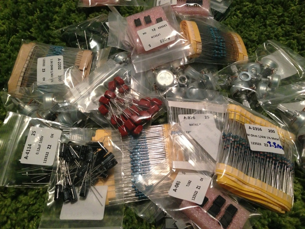
I decided to place order to a few places just to get an idea how long ship times are to me. Here is what I have gathered so far.
Small Bear Electronics
Order Date: 02/23/13
Ship Date: 02/27/13
Received: 03/04/13
Order was in full and complete
Adafruit Industries
Order Date: 02/26/13
Ship Date: 02/27/13
Received: 03/02/13
Order was in full and complete
Tayda Electronics
Order Date: 02/24/13
Ship Date: 02/26/13
Received: 03/04/13
Order was in full and complete
I will add other to this list as I order from other vendors.
Happiness in a chip
If I could only have 2 pedals for the rest of my life, I would take a reverb and delay pedal. I didn’t realize how a delay pedal worked until I attempted to make a few of them. I have found a life long relationship with the PT2399 chip and yearn for more insight on the little 16 legged beast. This is the IC behind many delays on the market and it is dirt cheap. Here is the schematics of a PT2399.
Here is the datasheet
Bench utility update
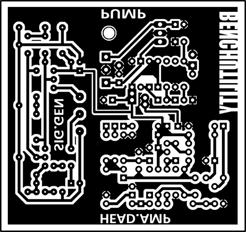
Bench utility PCB etched
Bench Utility V1
Here is my first attempt at combining a couple PCBs and tying in the power together. There will most likely be some changes. I am etching this board tonight to mess with and see how the shared power works out.
Each circuit individually has been verified by its designer and DIY communities.
It is a combination of 3 PCBs made by other people. I do not take any credit for making these designs individually, I just combined them for a neat/clean build.
What circuits are they?
- A basic 1hHz audio oscillator with a symmetry adjustment designed by R.G. Keen. I will be addig a DPDT toggle to switch between input jack or an audio probe.
- A charge pump / voltage inverter that can supply +9v -9v +12v +15v +18v designed and laid out by Madbean.
- Headphone amplifier designed by JMK Pedals.
Whats left?
I have an order of some parts I am waiting for but I am thinking of building this in a 1590BB so its not to large and takes up to much space on the bench.
New test rig thoughts
I have been rolling the idea around about building a new test rig and I have been reading up as much as possible on the subject. I have come to the conclusion I need to list out what I expect from it. So lets try this.
Most of this will be common knowledge but I wanted to get the thought process out.
Testing:
- Ability to hook up a PCB via clips and play an instrument through it.
- I would like to use headphones also. Added a switched headphone amp would be ideal.
- 1/8″ input for iPad/iPhone input to test with.
- Ability to bypass the circuit all together like a normal boxed pedal.
- Voltage sag control
- Charge Pump with -9v +9v +18v
- Connection buss for all test leads
Troubleshooting:
- Tone generator to use in conjunction win a oscilloscope.
- Switch between input jack or a testing probe.
Here is what I’m thinking of using so far:
Madbean’s Charge Pump “RoadRage”
R.G. Keen’s Quick and Less Dirty Oscillator
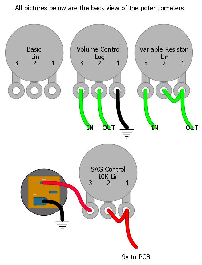
Potentiometers for the masses
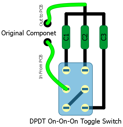
Switching between 3 components
I was working on a few Devi Ever clones and wanted to make 1 pedal that can be shaped into 3 different pedals. Devi is know for using 1 PCB for 3 or 4 pedals with just a few component changes. I wanted a way to wire a switch to change between 3 different capacitors or 3 different resistors. Here is what I have found.
I laid this out in DIYLC to give an example. The switch is a DPDT on-on-on Toggle Switch
You will be able to do the same thing with resistors. Just replace C1-C3 with the needed resistor values.
