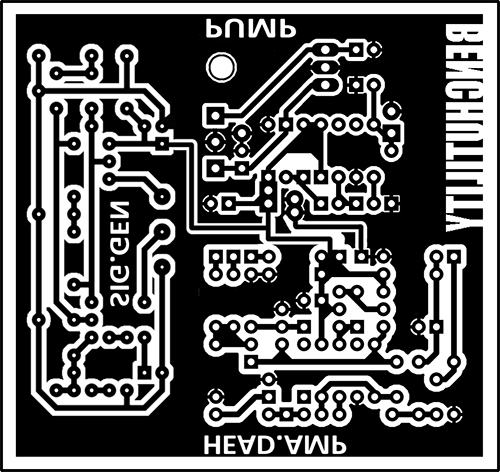
Bench utility PCB etched
Just need to trim it up a bit.

Just need to trim it up a bit.
Here is my first attempt at combining a couple PCBs and tying in the power together. There will most likely be some changes. I am etching this board tonight to mess with and see how the shared power works out.
Each circuit individually has been verified by its designer and DIY communities.
 What is is?
It is a combination of 3 PCBs made by other people. I do not take any credit for making these designs individually, I just combined them for a neat/clean build.
What circuits are they?
Whats left?
I have an order of some parts I am waiting for but I am thinking of building this in a 1590BB so its not to large and takes up to much space on the bench.
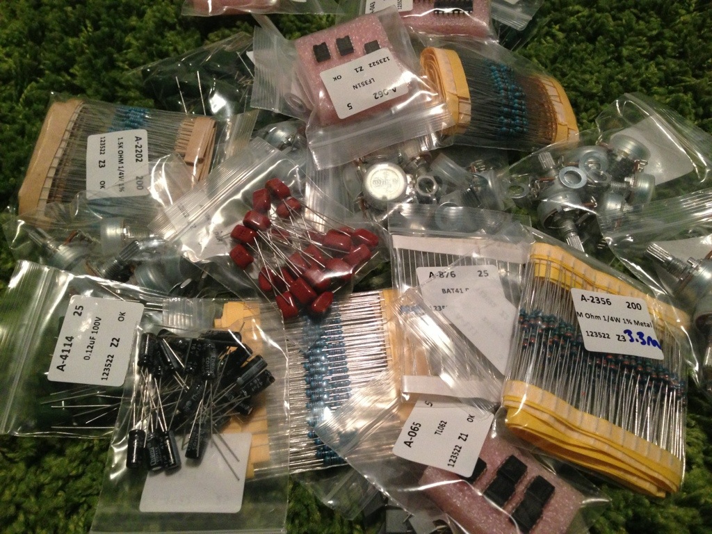
My Tayda order got her tonight. Finally can finish up a few builds that have been laying around.
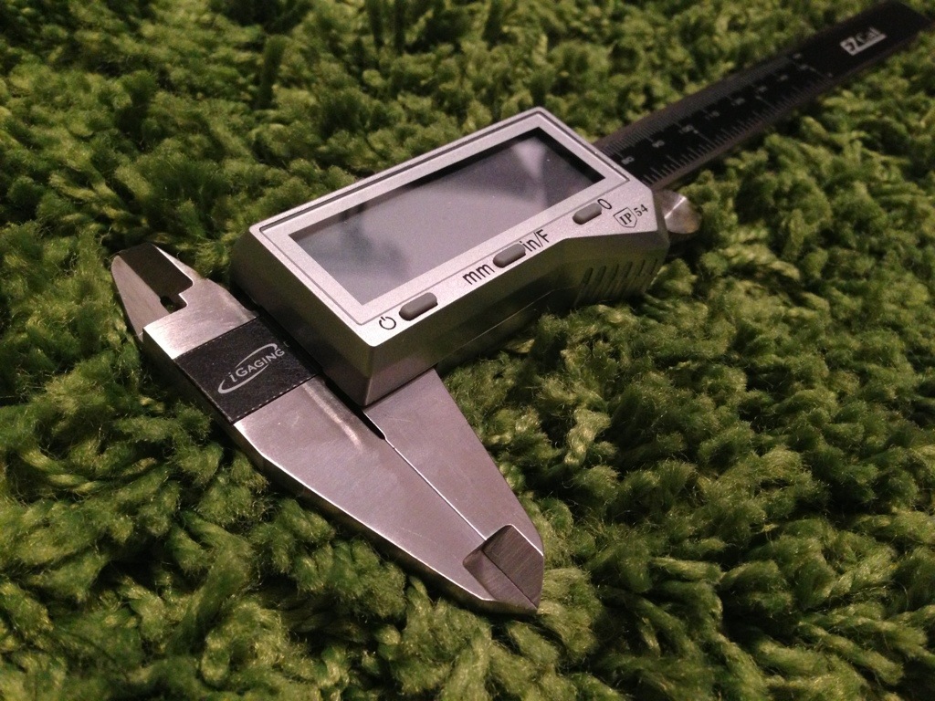
I have been looking for a decent set of these and just did not like the feel of the Harbor Freight ones. I hit up Amazon and read some reviews on a few different models and also looked at eBay reviews and got about the same results. I then found a few guys on a DIY Audio forum that were talking about these and how much they liked them and how surprisingly accurate they were for how for the price. I picked them up on eBay from a company in the Bay area new for $22. I am happy with the build quality and can’t wait to use them on my next 1590A build and others.
A list of part houses:
Jameco Electronics
1355 Shoreway Road
Belmont, CA 94002
Place an Order
Phone: 1-800-831-4242
Fax: 1-800-237-6948
Email: Sales@Jameco.com
Mouser Electronics
1000 North Main Street
Mansfield, TX 76063
Toll Free: (800) 346-6873
Phone: (817) 804-3888
Fax: (817) 804-3899
Email: sales@mouser.com
Mammoth Electronics
3203 Broce Drive Suite B
Norman, OK 73069
Phone: 1-405-254-4112
Email: sales@mammothelectronics.com
Small Bear Electronics
123 Seventh Avenue #156
Brooklyn, NY 11215
Pedal Parts Plus, Inc.
14594 Hwy. 111
Anacoco, LA 71403
Phone: (337) 286-9859
Fax: (337) 286-9582
Email: Sales@pedalpartsplus.com
Thai Shine Company Limited
160/67 Soi 28 Rama 6 Road
Samsennai, Payatai
Bangkok 10400
THAILAND
Antique Electronic Supply
6221 South Maple
Tempe AZ 85283
Phone: 480-820-5411 (8-5 MST, M-F)
Fax: 1-800-706-6789
Email: sales@tubesandmore.com
info@tubesandmore.com
Allied Electronics, Inc.
7151 Jack Newell Blvd. S.
Fort Worth, Texas 76118 U.S.A.
Support: (866) 433-5722
1547 N. Trooper Rd.
Worcester, PA 19490
Local Phone: 610-825-4990
Toll-Free Phone: 800-832-4866
Fax: 800-854-8665
Phone: (800) 408-8353
Email: customer.care@avnet.com
I want to build one but it has to have the tone pot mod. I love the sound of it and I just need to figure out a good PCB for it. I might have to trace a vero one to make a PCB. Hmm.. Here are some notes I found.
LaoWiz says:
The middle knob is a 5k pot to vary the mid scoop filter on the end of the circuit. When the scoop is omitted (knob all the way up), a lot of the volume loss from the scoop is regained. Still, I would like it a touch louder. What I have found is that 3904s and any other plastic case transistor sounded like s**t in here. I used BC109B and BC108B for Q1 and Q2. Sounds WAY better IMO. More buzzy. I am currently building two for a couple of friends but am adding the boost on the end of the circuit. But instead of using a 3904, I am using a metal case 2222A. Again, sounds way better. I also tested out different capacitor types. I used ceramics for the most part and some vintage caps from my local surplus store for the 1000, 2000, and 3000pf spots.
I will work on a PCB layout and get back to this post.
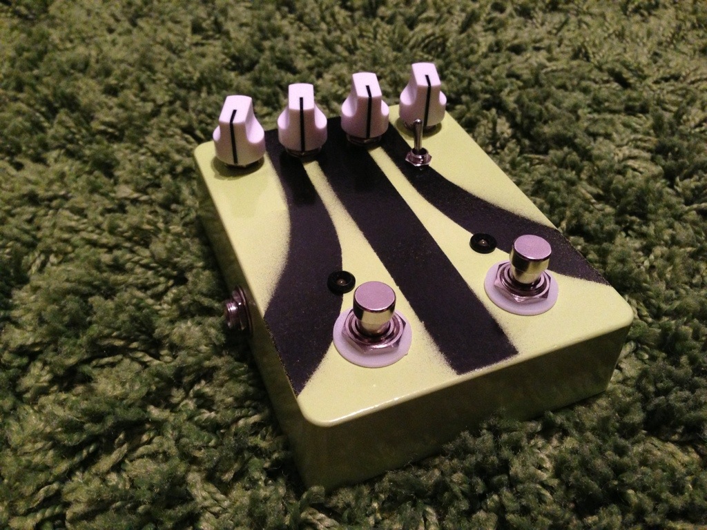
Finished this pedal today. I hope to get some clips of it up soon.
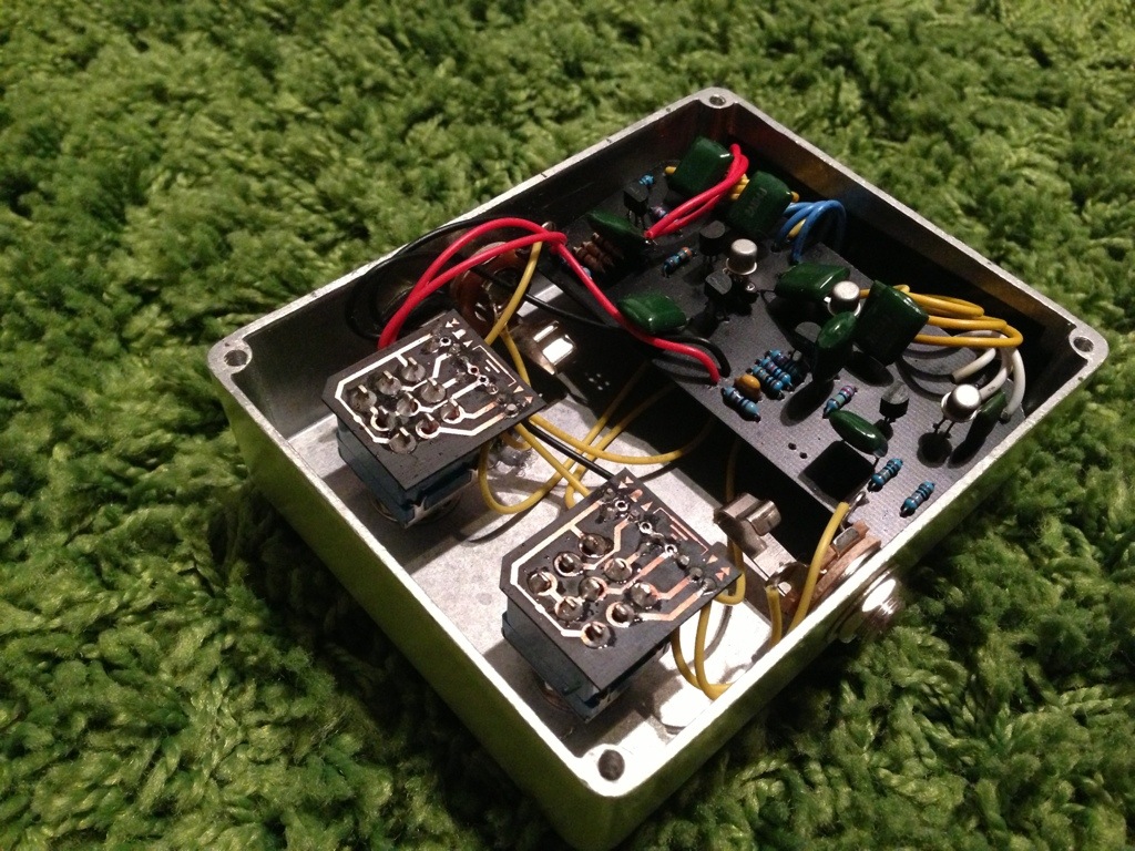

I decided it is time to upgrade my test pedal to something with a bit more troubleshooting power. As of right now I have a pedal with some alligator clips so I can hook up a non-boxed pedal and test it. Just a basic enclosure I learned to wire up from Beavis Audio. Here is the basic idea of what I want in a 1590BB enclosure.
Seeing how it is 4:53am and this just poped in my head, stay tuned for more info on this. Now I have to make up my mind if I should try to sleep or keep playing Far Cry 3 on the PS3.
This is not a recap of the book Communion: A True Story (1987). This is some notes on audio probing and troubleshooting your circuit These are not my notes since I am trying to grasp how to accomplish this technique. I have just found notes from various places and I am archiving them here.
guitarmageddon Wrote:
OK, my world was turned upsidedown by the building of an Audio Probe. Can’t say enough good things about using one. Put simply, it lets you evesdrop on what’s happening at any given point in your circuit.
You need your guitar plugged in to the pedal, the pedal powered up and on and the amp on. The guitar needs to be producing sound. If you’ve got one, record something into a looper so you’ve got your hand(s) free.
The probe sheild is connected to the pedal earth (case or out put sleeve) and the tip goes to the amp’s input.
Start by strumming the guitar and touching the probe tip to the input jack tip. You should have signal as if in bypass.
Try the switch next, lug 4 (of the BYOC type bypass) should also have the input signal.
Now lug 5, the effect input, should still hear input signal.
After this it’ll get more interesting.Check your board’s input, then, followig the schematic, trace the audio path as it flows through the curcuit. listen to both sides of each componant. (Anything connected to ground will be silent on the earth side)
You should be able to hear changes, capacitors affecting the tone, resistors dampening the signal strength, etc, Transistors should amplify the signal from what it sounds like at the base, to what it sounds like at the collector. Don’t forget to listen to the pot lugs either.
Assuming your pedal produces no output, what you’re looking for is where the audio signal stops.If you’ve got some idea of where the problem might be, go straight to there and listen up and downstream.
Also, if things go dead inexplicably at some point, check that there isn’t a short to ground by using a DMM in continuity setting. Connect one probe to ground (screw hole of enclosure) and probe the signal path. Unless there’s a short, there shouldn’t be any continuity.
duhvoodooman Said:
When I first started using it, I found it much easier to understand the hook-up & function of a signal probe by thinking of it merely as a “movable output jack”. Plug your output cable into the jack of the signal tester, hook the black wire clip to ground (the solder tab for the sleeve of the input jack is always a good choice), and then touch the red probe to wherever in the circuit path you want to check.
more to come…