Category: DIY

Black Arts LSTR

-This is unverified – Hope to verify it this weekend.

There are some hard working people at Madbean forum that have been working on a great spreadsheet with a bunch of Big Muff variants on it. I wanted to contribute is some way and I found that no one has picked apart the LSTR for the list.

There was a schematic that was posted in FSB forums.

Mark over at Tagboard Effects made a vero layout for it.

Since we at the Madbean forums use the Mudbunny PCB as a primer, I have matched the parts from both the FSB schematic and the Mudbunny and this is what I came up with.

Madbean Mudbunny Build Doc

This is the BOM for the Black Arts LSTR built on a Mudbunny PCB.

Resistors Capacitors Diodes
R1 1M C1 100n D1 – D4 1N914
R2 39K C2 560p D5 1N4001
R3 100K C3 100n
R4 470K C4 100n Transistors
R5 100R C5 560p Q1-Q4 MPSA12
R6 15K C6 100n
R7 1K C7 100n Pots
R8 15K C8 560p SUS 100KA
R9 100K C9 100n TONE 250KB
R10 470K C10 1n MID 50KB
R11 100R C11 10n VOL 100KA
R12 15K C12 100n
R13 15K C13 100n
R14 100K C14 100uF
R15 470K C15 100n
R16 100R
R17 15K
R18 68K
R19 MID POT
R20 470K
R21 100K
R22 15K
R23 1K2
R24 100R

Excel Spreadsheet in juansolo’s format

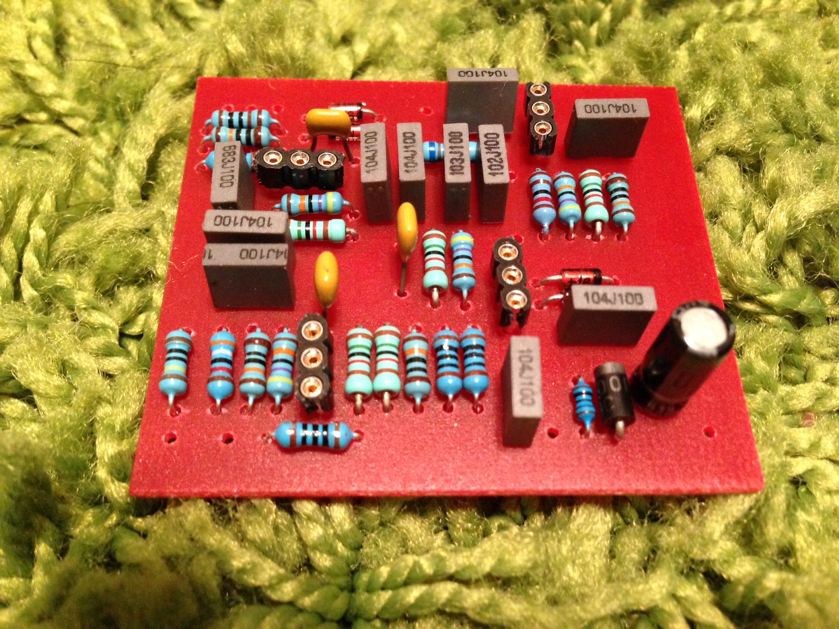
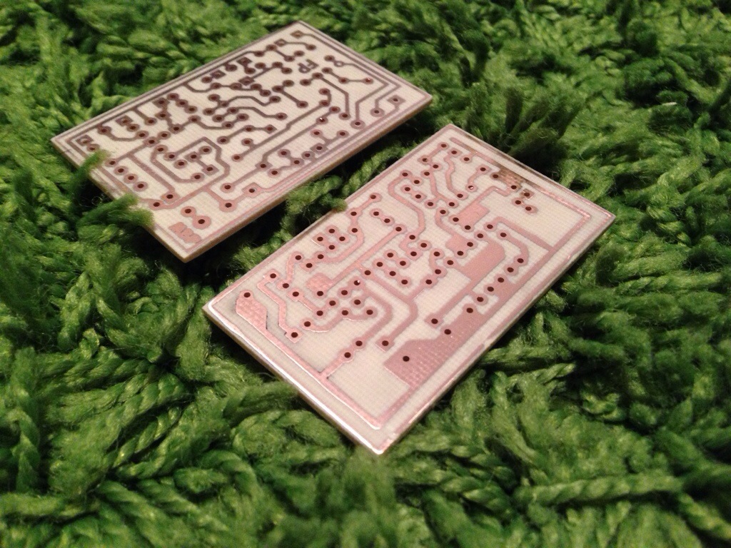
Update: populated the Mudbunny this weekend but I need to do the off board wiring. I hope to work on this tonight.

Updated:

Populated

photo 2

Strymon Timeline MIDI controller

Looking at making a MIDI controller for my Timeline and wanted to look at a few options. First off the retail units I have been reading about.

Tech 21 MIDI Mouse
Disaster Area MMC-3
PedalSync OZ

I am really wanting to take advantage of the Full/Half speed toggle and the reverse and Undo functions. To start out I will most likely look at doing a 3 footswitch box just for those functions until I can learn more about how to have mode switching like the Disaster Area units have.

Strymon Timeline MIDI implementation chart for looping functions:

You can set up your MIDI controller with either MIDI CC (continuous controller), or MIDI note numbers.

MIDI CC values:

  • Record – CC# 87, any value
  • Play – CC# 86, any value
  • Stop – CC# 85, any value
  • Reverse (toggle) – CC# 94, any value
  • Full/Half Speed (toggle) – CC# 95, any value
  • Pre/Post (toggle) – CC# 96, any value
  • Undo (to initial loop) – CC# 89, any value
  • Redo – CC# 90, any value
  • Looper Level – CC# 90, value range 0-17

Note values:

  • Record – note 0, velocity > 0
  • Play – note 2, velocity > 0
  • Stop – note 4, velocity > 0
  • Reverse (toggle) – note 14, velocity > 0
  • Full/Half Speed (toggle) – note 16, velocity > 0
  • Pre/Post (toggle) – note 17, velocity > 0
  • Undo (to initial loop) – note 7, velocity > 0
  • Redo – note 9, velocity > 0

I was thinking about doing a Arduino project but figured it would be to bulky and to much unneeded overhead. I think a basic PIC with a small program to translate the MIDI values will be my best option.

More to come…

Black arts Toneworks Pharaoh clone

I used a Madbean Mudbunny as a base PCB for this great big muff pi variant. This thing just screams “stoner rock” at its finest. I am really starting to like the diode switch set to no diodes, it sounds so harsh.. in a good way. The High/Low input switch I found pretty useless in my situation since the high setting always sounded better to my ears. I will need to see what the real purpose of this switch is.. I might not understand its usage clearly.

20131008-222532.jpg

20131008-222539.jpg

Unicord Superfuzz

Finally.. FINALLY.. I got a working layout. I had so many problems getting this to work and come to find out I had an old layout that had errors. Thanks to the guys at DIYSB they help to point me in the right direction. Now that its done I simply love this fuzz, it is my 2nd favorite fuzz with the v4 Big Muff OpAmp fuzz. This pedal nails that harsh fuzz that I was craving.

Here is the layout I used

20131008-003811.jpg

20131008-003819.jpg


I am a bit sad since I got this all put together and I dropped a screw driver on it and chipped the paint right next to the SPDT switch.

Modded Germanium Fuzz Face

I was looking for a Fuzz Face that got some of the low end like the Ox Fuzz and as much control as I can get out of it. I came across a layout by Ataraxia Engineering called the 4-Knob Fuzz Face. Its a basic Fuzz Face layout with a charge pump to make it a negative ground pedal. This pedal has a few of the more “well known” mods.

Here is the layout I used

20131008-003656.jpg

20131008-003704.jpg


Looks like the ground pour got the best of me with my solder. No biggie.. it sounds great.

1776 Multiplex Jr.

I just simply love this delay. Josh over at 1776 made a solid design and its bullet proof. This is the 2nd one I have built and I am not sure why but this one was a lot harder to fit in a 1590B. At the end of the day I finally got it fit and it came out pretty clean… oh oh .. and it sounds great too.

Here is the build Doc from 1776 Effects

20131008-003544.jpg

20131008-003552.jpg

I am debating if I should label the controls or leave it as is. Think I will toss it on my board and see how it goes.

Flexi Clip

I pulled the information from diy-fever and I wanted to make a quick PCB for it. I am trying to force myself to use Eagle but for something so simple I decided to use DIYLC for a quick layout. Here is a description of this pulled from diy-fever.

This circuits lets you try many symmetrical and asymmetrical clipping types combining few most used clipping diodes: Silicon, Germanium, Rectifier, LED and FET (used as diode: Drain and Gate for cathode and Source for anode). Below is chart of forward voltages I measured on all parts used here.

This is how mine turned out.

20131007-184656.jpg

20131007-184703.jpg

20131007-184711.jpg

Worked perfect and I was able to try a few different configuration with a Rat pedal I am building.

Testing new copper clad

I recently ordered some new copper clad from eBay and I noticed the prices of the red laminate that I like useing went up in price. I decided to jump on a deal he was having on 4″x6″ CEM (Composite epoxy material) single sided copper clad. I got a great deal on a 49 pieces so I jumped on it. I figured that if they don’t work well as PCBs then I can use them as faceplates. Here is the information I found on them.

20130923-211948.jpg

First thing I noticed was the copper was cleaned up pretty well and I just hit it with some 600 grit wet sandpaper before etching.
20130923-211956.jpg

It seemed to etch well and even.
20130923-212010.jpg

If I was going to complain about anything it would be the fact that CEM will chip when cut with my table top paper cutter. So I may have to use the jigsaw or Dremel.

DC Plugs for my test bench

A few months back I made a desktop PSU for my work bench and I thought the Madbean Road Rage charge pump would be perfect since I was able to get +9v -9V 12v & 18V all in one box. I needed to make some DC jacks for the PSU and decided to spruce it up a bit with some easy to find parts. This is the items I needed for this project,

  • DC Power Plug 2.1mm – I grabbed these since they were cheap and did the job.
  • 18 Gauge Speaker wire – I’m not sure where I bought this since it was a stash I had in my garage.
  • Black Paracord – I love this stuff but it can be a pain to work with. I suggest taking your time and making sure you use something very sharp to cut it. Also, make sure it does not fray to much, I use a lighter to melt the end a bit.

20130923-211657.jpg

20130923-211707.jpg


I cut the wire and paracord to the same length. You might need to cut the paracord a bit longer due to the diameter of the cable may shorten the overall length of the paracord.

20130923-211719.jpg


Remove the white nylon strings from with in the paracord. They just pull right out with no effort.

20130923-211729.jpg


I found it 4000 times easier to put the DC jack plastic covers on the paracord before feeding the wire through. Experiment and rinse and repeat.

20130923-211741.jpg


Now for the slow part of this process, feeding the wire into the paracord. Think of the paracord like a “chinese finger trap” and you need to push the paracord together to expand it. I know.. I Know “what the hell is her talking about”, trust me, you will figure it out.

20130923-211752.jpg


All done, that wasn’t to bad, right?

20130923-211801.jpg


I trim the ground wire back a bit (In this case I used the wire with this white stripe on it) so I can solder it to the sleeve of the DC jack.

20130923-211810.jpg


Shazam, all soldered up. wow this picture makes it look like a pretty bad job but since the ground wire was trimmed there is a very low possibility for a short.

20130923-211820.jpg


Here it is all put together. I think the paracord just makes it look so clean.

20130923-211832.jpg