DIY Monome TeleType
On Nov 26, 2019 Monome released their TeleType eurorack module to the world under the Creative Commons (cc-by-sa-3.0) to GitHub. They made available the Gerbers and front panel files along with a BOM. I have wanted one of these modules for awhile, but it was hard to take the $500 plunge. It has such a steep learning curve and I was afraid I would not dedicate the time it needs to learn it.
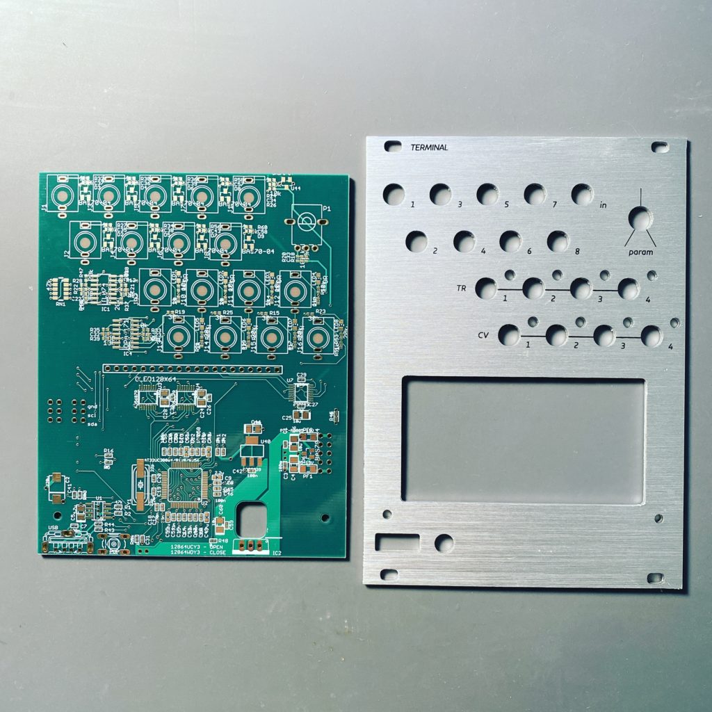
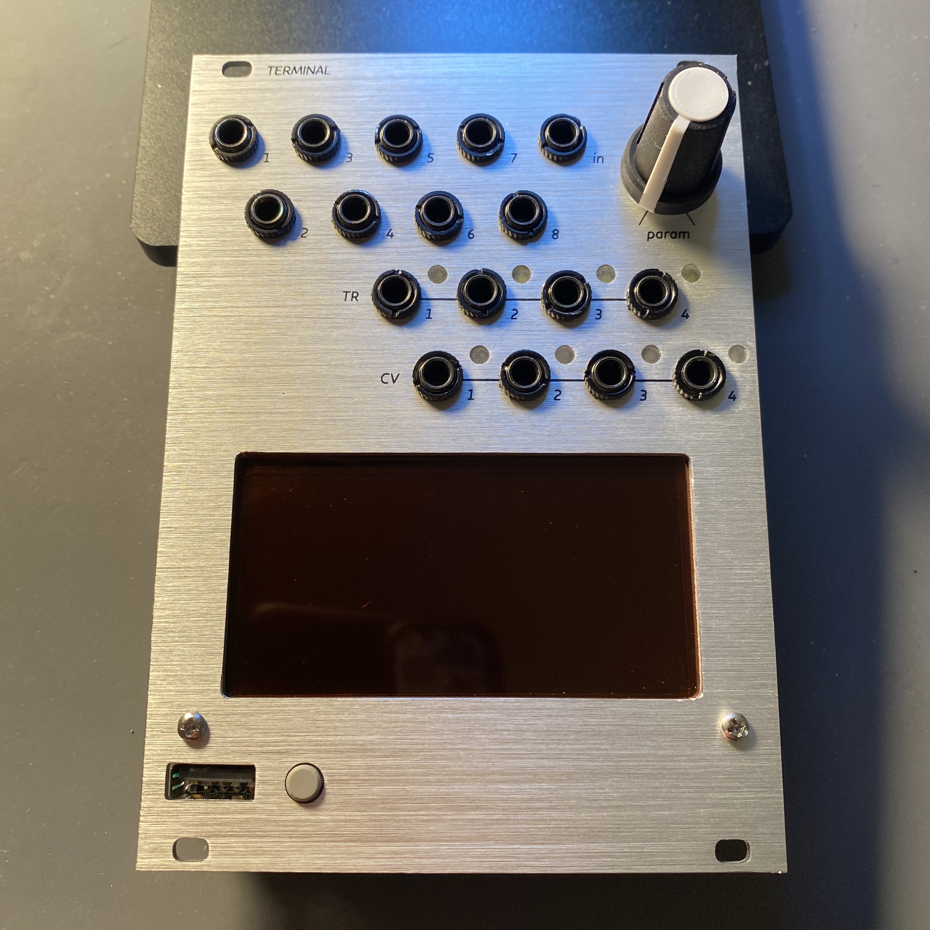
I just happen to check Pusherman’s store out to see what new PCBs he had available since I was itching to build something. To my amazement he was offering the TeleType PCB/Panel under the name “Terminal”.
I quickly made a BOM on Mouser for the needed parts and I quickly noticed this project uses 402 SMD parts.. TINY parts.. The smallest I have done to this date was 603 and even that was a bit nerve wracking. I really wanted to build this thing so I decided to give it a go.
I made an export of the PCB in EagleCAD to help ID the part locations since the PCB silkscreen is hard to decipher at some points.
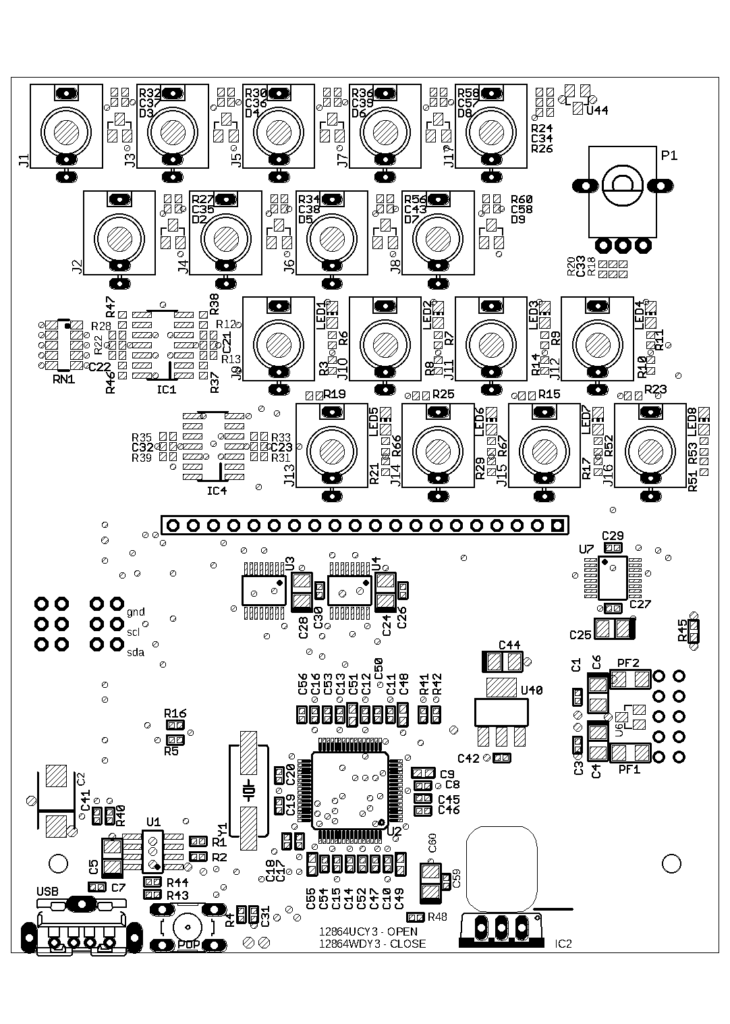
Its so weird to be more afraid of all the resistors and capacitors over needing to soldier the AVR.
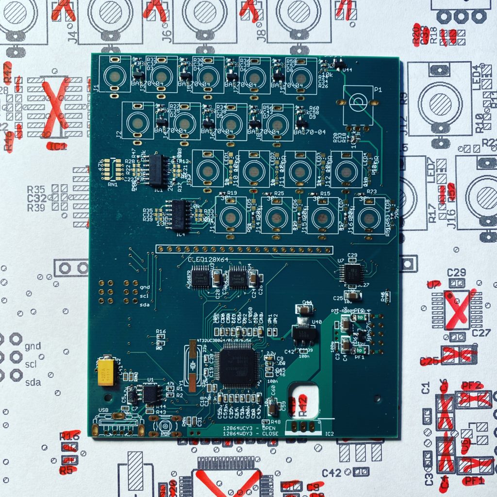
I mostly got the PCB populated and was waiting for a couple parts that were not in the BOM.
USB Cable:
To flash the AVR it was really easy to use Monome’s instructions with a USB-A to USB-A cable. I did not have a cable and needed to make one. Just cut a couple USB cables you have laying around and match the RED, WHITE, GREEN, BLACK and you will be fine.
Follow the instruction from Monome’s website for firmware flashing
I wanted to test all the LEDs and voltage from all the in/out jack pads before I installed the jacks. Once the jacks are soldered in it will be difficult to troubleshoot the parts between them.
Protip: If you are having issues with the trigger out LEDs, its most likely IC1 or the capacitors and resistors around it. Take the time to look at each of these and touch up soldier if needed.
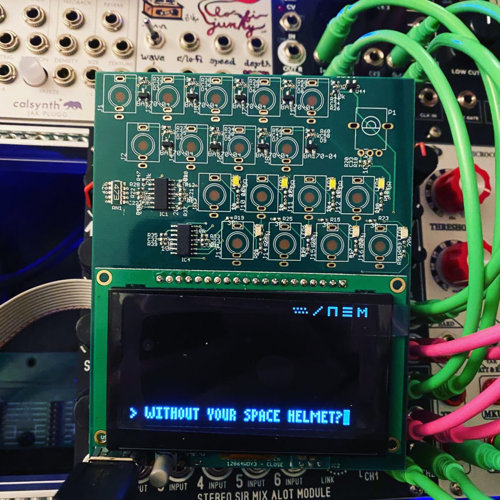
Got everything mounted and now I am just waiting for my B10k pot (apparently I only had plastic shaft trimmers on hand) and the mounting hardware for the OLED LCD.
Notes:
1) Trim the pins of the LCD header so the LCD is not higher than the jacks.
2) All of the LEDs on the PCB are orientated with the anode on the lower pad.
3) There is a small jumper that is needed if you use the 12864WD LCD I have in the BOM. The jumper is located just under R4 and C31.
Resources:
Mouser Project I created
Monome TeleType Hardware GitHub
Monome TeleType Firmware GitHub
Lines Forums thread
Muffwiggler Forum thread
5 comments