Category: Tips

PCB Etching

I wanted to share my current process for etching a PCB from scratch. Here is a list of supplies I used in this tutorial.

Items I needed:

  • Copper clad board (I use 1oz copper 030 thinkness, This might be to thin by some standards but it works well for me. I like to trim/cut my boards with household scisors.)
  • Laser Printer (HP LaserJet Pro P1102w with ePrint) I set the Print Density to 5 in the menu settings on the printer itself.
  • HP Glossy Presentation Paper (Office Depot/Max $6.99)
  • House hold iron (I use a Black & Decker household cloths iron)
  • Ferric chloride solution (You can get a bottle from Radio Shack that should last for  10-15 smaller PCBs)
  • Plastic containers with lids (Rubbermaid sandwich containers)

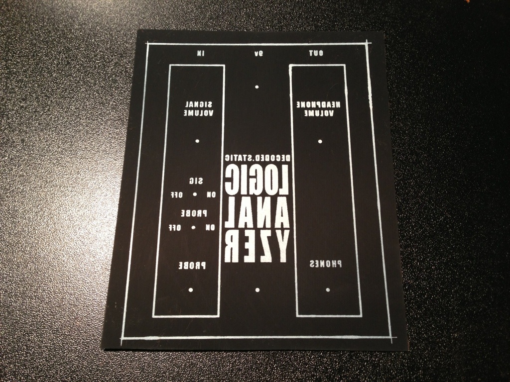
Create a layout or find one online. I use Adobe Photoshop to size the image to 300 DPI (seems to be the standard for PCB transfers)

(Placeholder for PSD file)

I print the image on PhotoPaper on a Hp Laserjet. I make sure I set the output the “best” quality.

image

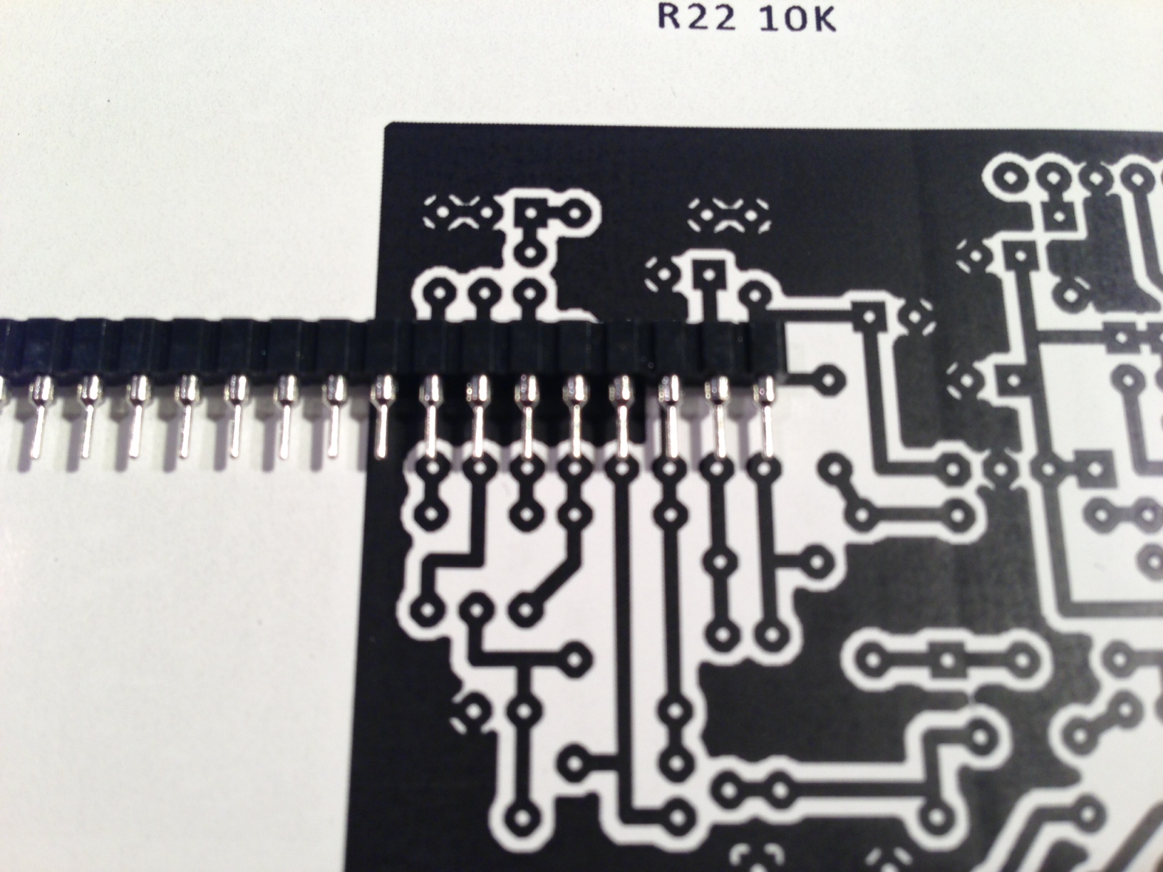
Check and make sure the sizing is correct of the printout. I use some SIP sockets to make sure the layout lines up.

image_1

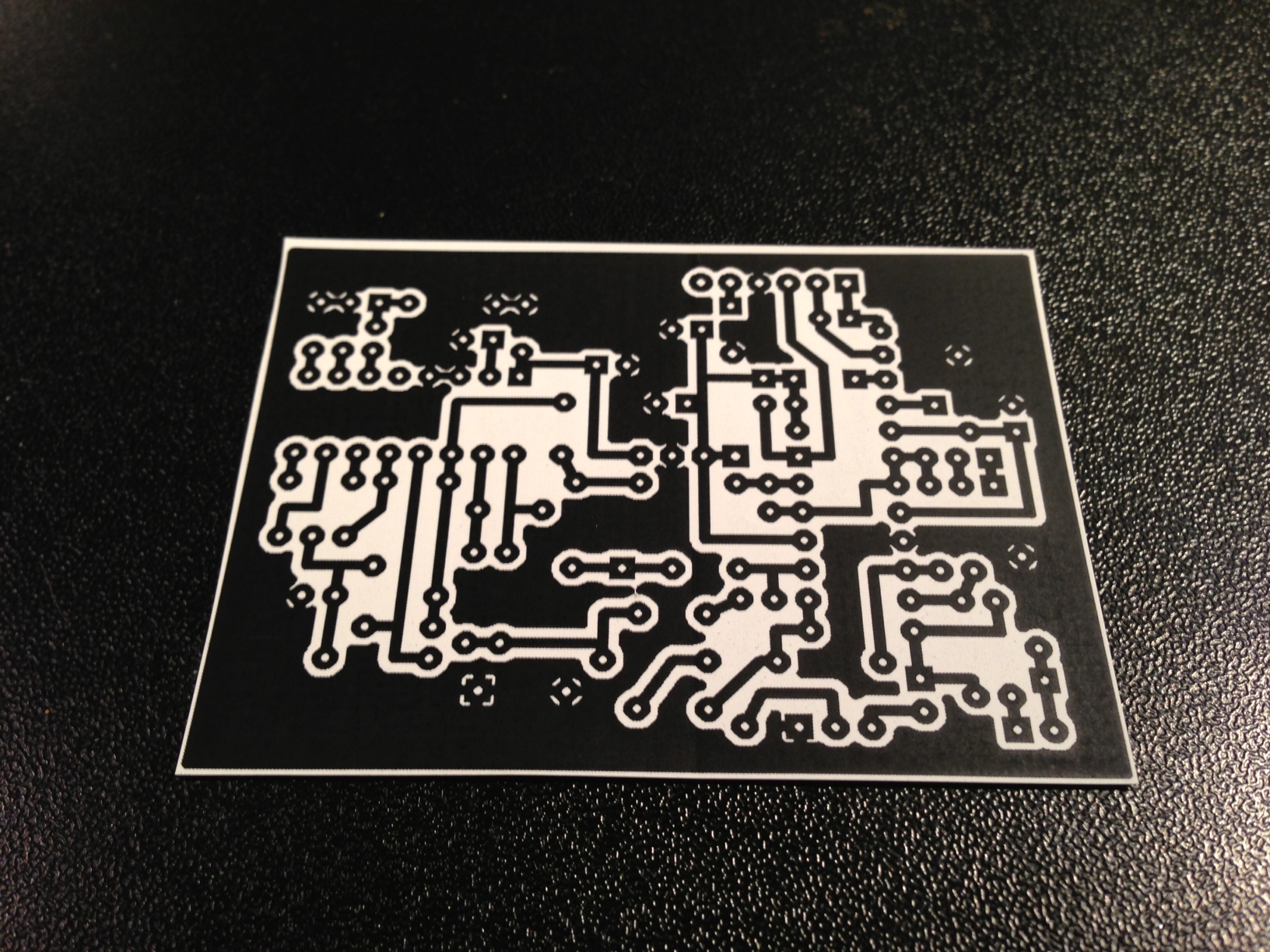
Cut out the PCB transfer

image_2

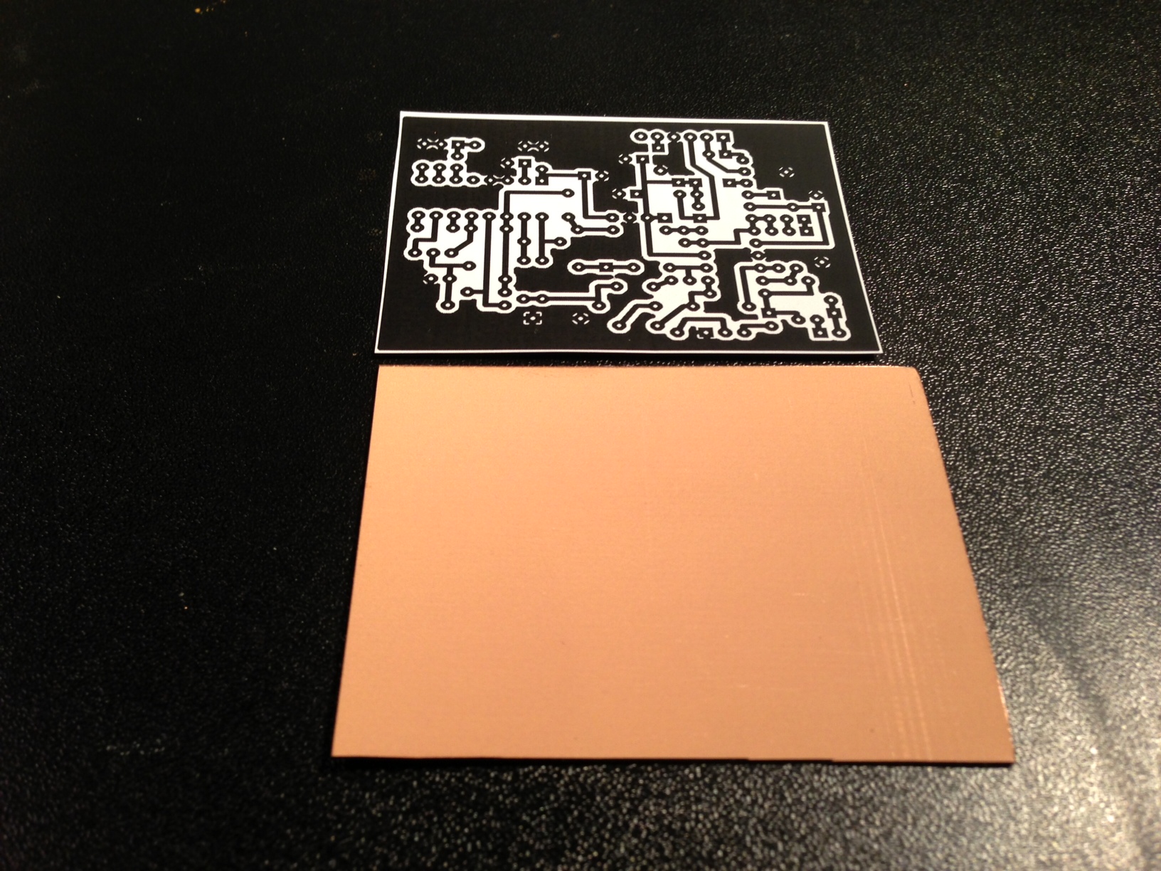
Cut a piece of copper clad board that is a little bit larger than my PCB transfer. This is just to make sure my edge of the design gets transferred to the clad board.

image_4

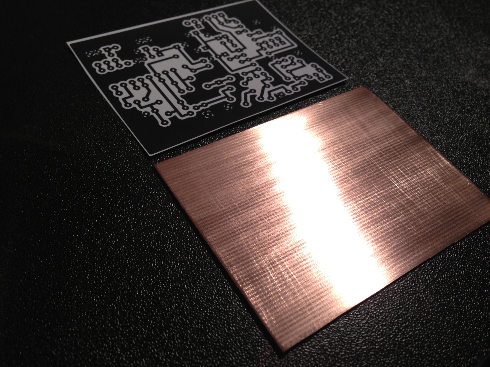
My copper clan has a protectant on it that needs to be ruffed up or removed. I usually sand the board with 600 grit wet/dry sandpaper. This has worked well for me.

image_5

I place the PCB transfer face down on the copper clad.

image_6

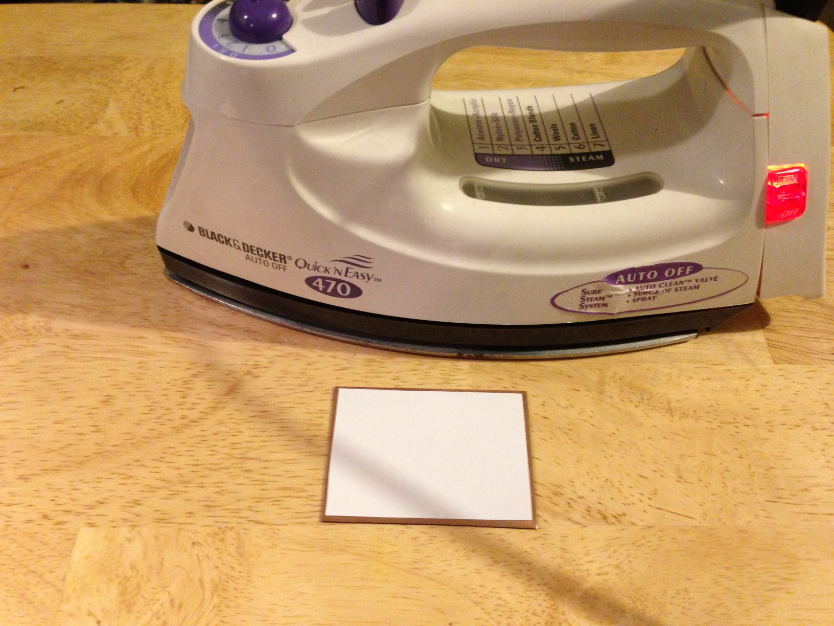
I set my household iron on maximum setting and let it warm for a few minutes. I place the iron flat on the copper and press down for 15 seconds just to get the PhotoPaper to fuse/stick to the copper clad.

I the use the tip of the iron to run in small up and down patterns across the PhotoPaper. I do this from top to bottom then rotate the copper 90 degrees until I have rotated the clad 360 degrees. You should be able to see the traces through the PhotoPaper.

image_7

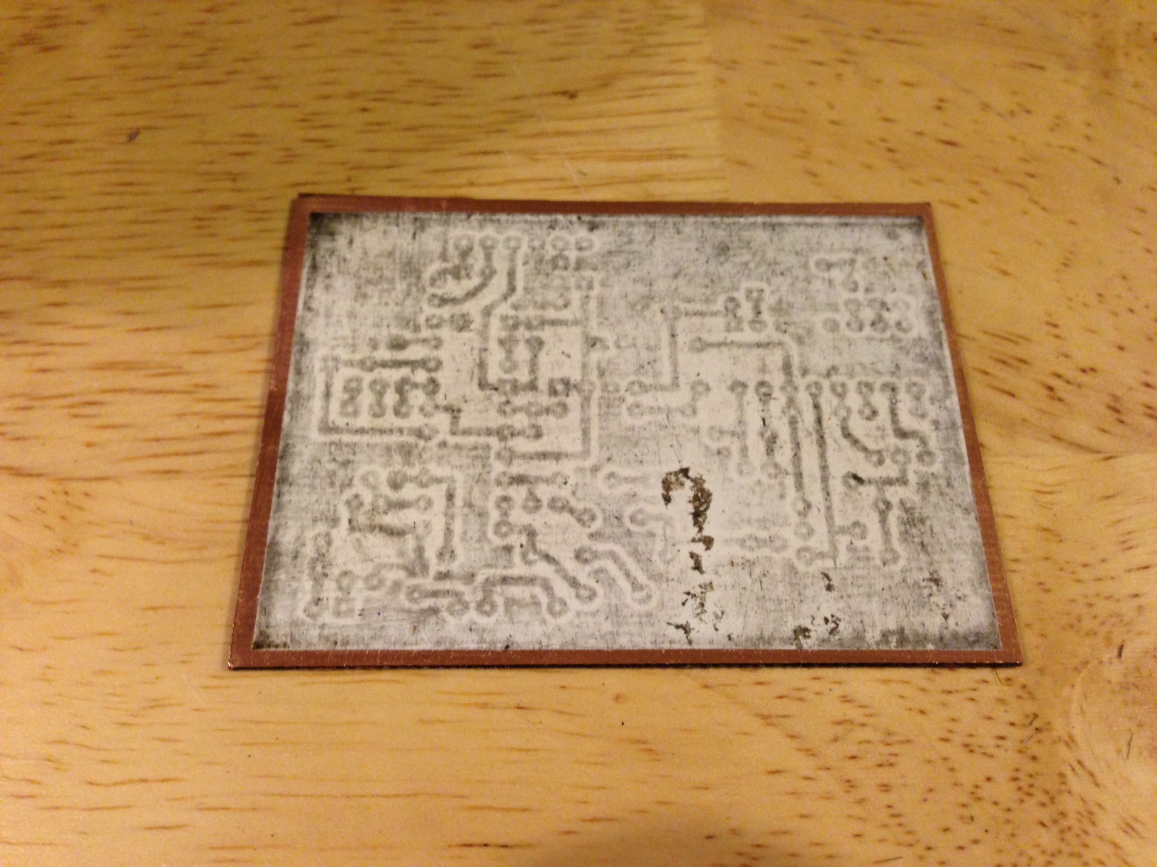
I let the copper clad cool for 5 minute and set up a small bath of warm water will a little dish soap in it to soak the copper clad in.

image_8

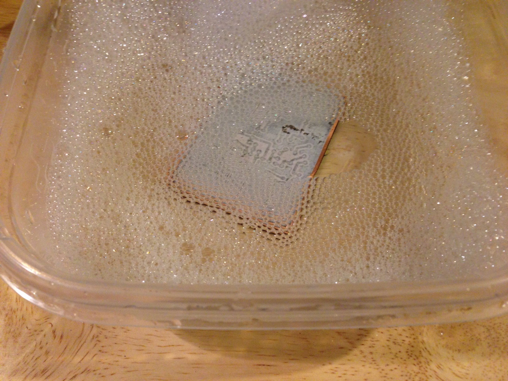
Remove the PhotoPaper from the clad the best you can with your fingers. I then use the scrubbing side of a sponge to gently buff the copper clad to remove all the PhotoPaper. I have done this to 25-30 PCBs and I have never removed a trace by accident. Just don’t be aggressive with the buffing.

Before the “gentle” buffing: Don’t mind the nasty looking sponge. Its been used on a few PCBs in the past.

image_10


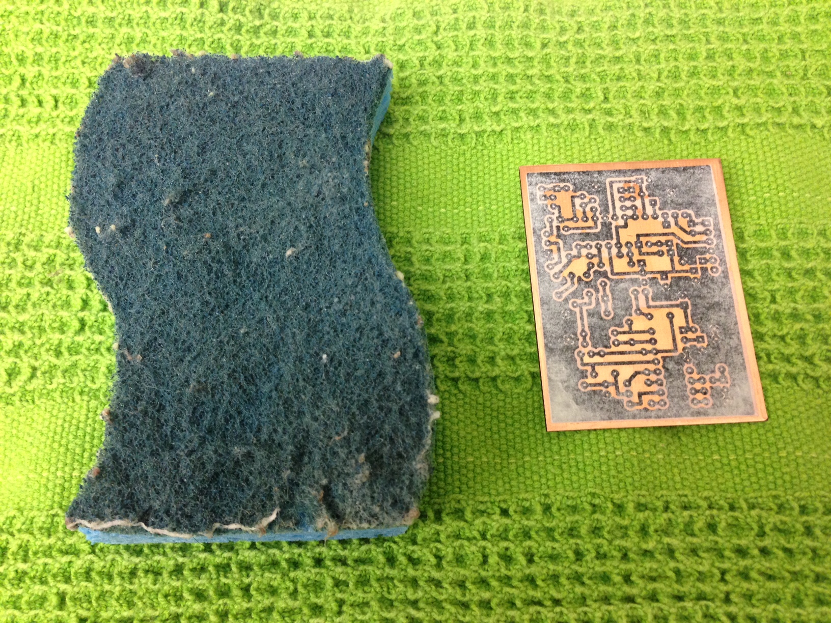
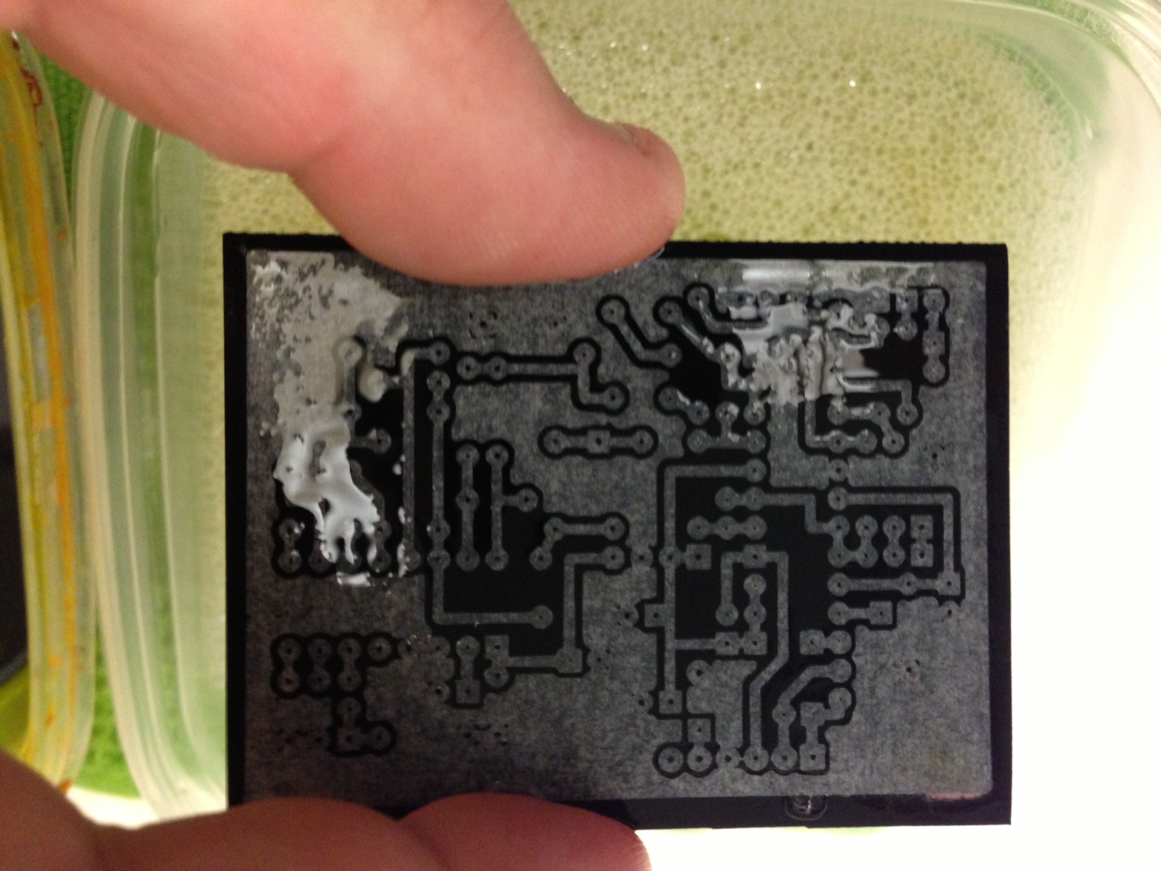
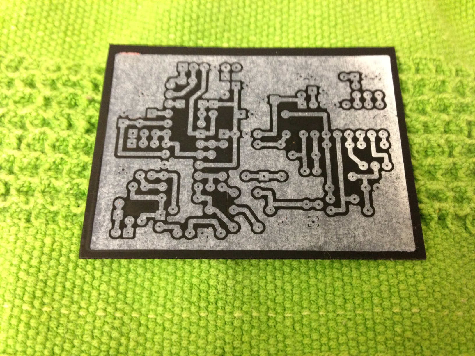
After the light scrubbing. Now that I’m looking at the photo I bet I could have scrubbed a bit more. I noticed a little bit of paper on the bottom left hand corner.

image_11

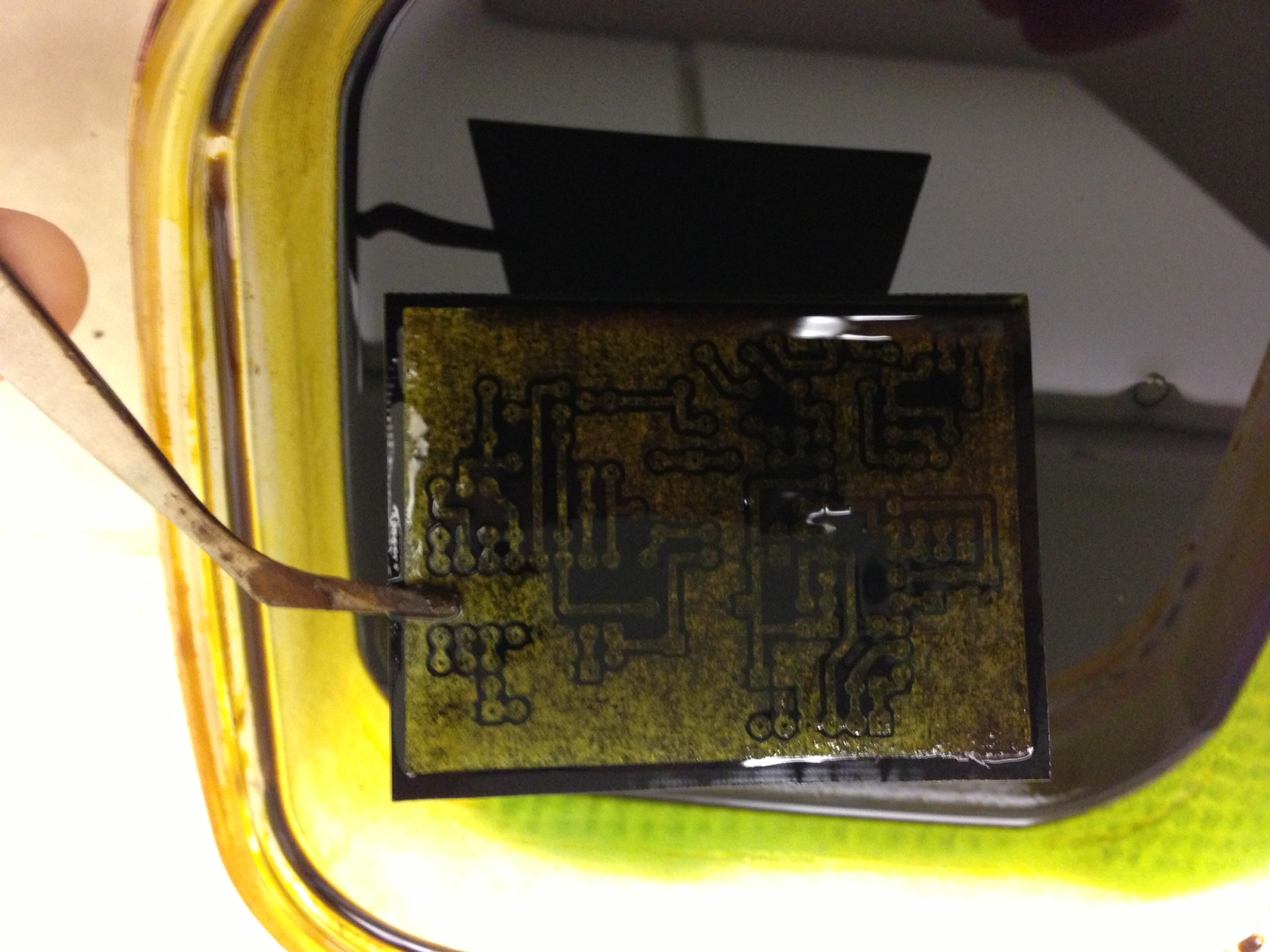
I take my container of etchant and place it in the microwave for 5-10 seconds. I then place the container of etchant on my etching rig and dip the copper clad PCB in. You do not need a rig to do this, just use your hand to rock back and forth (agitate) the chemical to speed up the etching process.

image_13

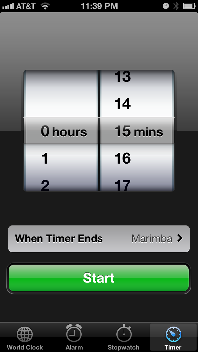
I set my alarm for 15 minutes and check the progress. Use plastic tweezers to pull the PCB out and inspect the traces. If you see any copper then place the PCB back in the etchant and recheck it every 5 minutes.

I seem to like to etch boards at 11:39pm (don’t tell the wife)

image

This is also the point where I say do not use metal tweezers since they will begin to get eaten away by the etchant.

image_16

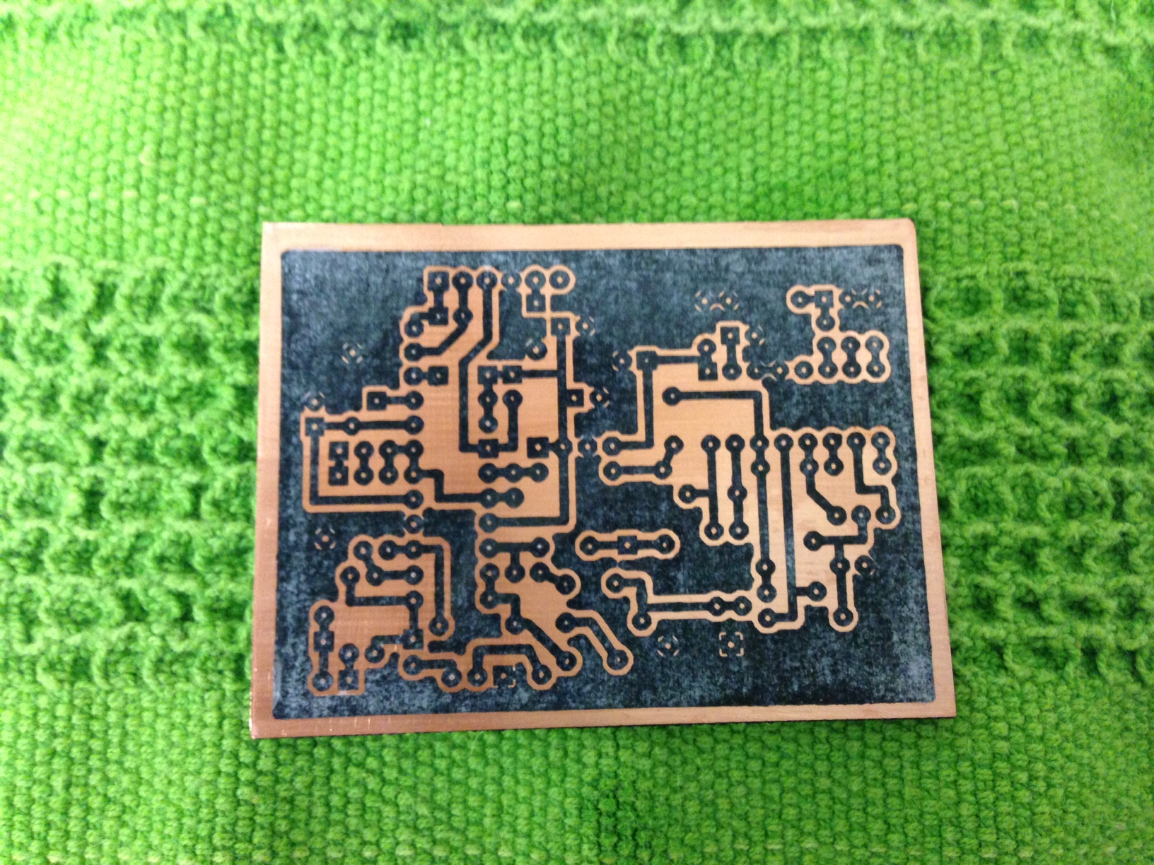
Once all the visible copper is gone, remove the PCB from the etchant and give it a wash in cool water and dry with a towel.

image_17


image_18

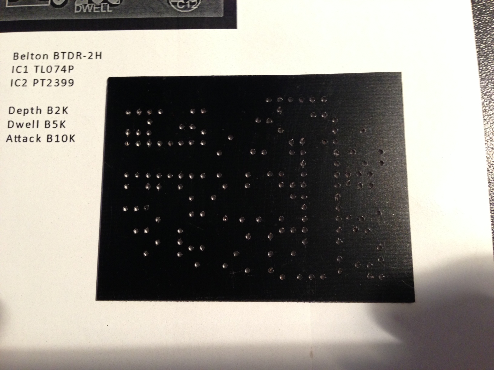
I now take the PCB to my drill press and begin to drill out all the pad holes.

image_19


The holes look a bit on the larger side. Maybe I should drop down a size on my bits…hmm.


image_20

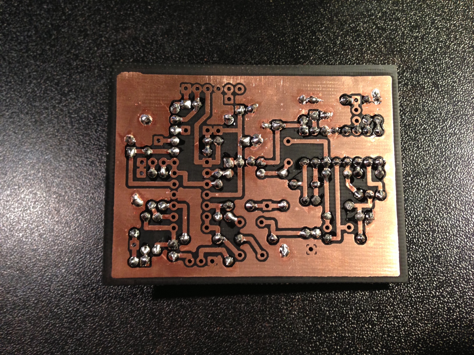
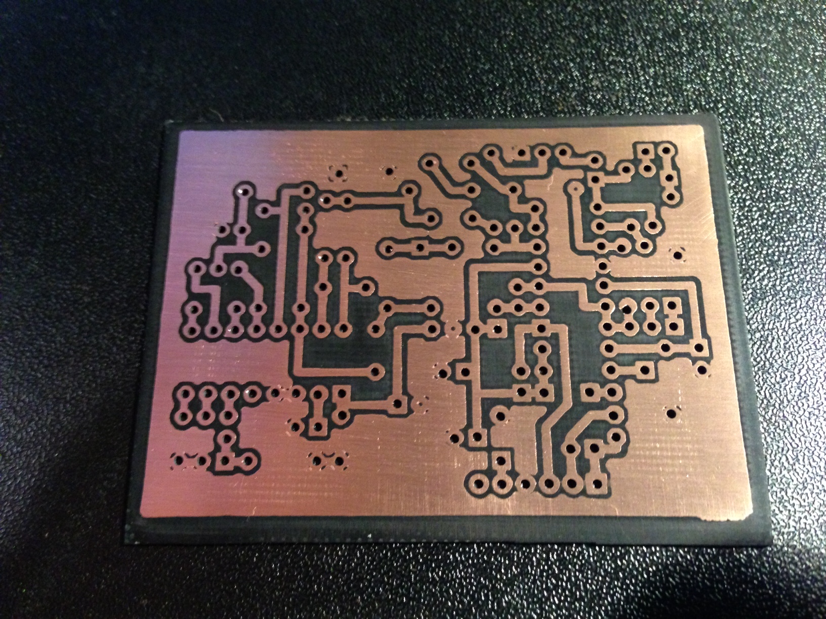
I take some 600 grit sand paper to remove the toner from the traces. Inspect all traces and look for any shorts. When I first started the toner method I would use a digital multi-meter and test each trace but now I am comfortable with not testing each trace.

image_22

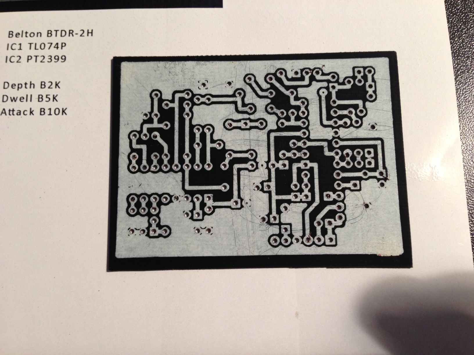
If I’m not going to populate the board within 48 hours I leave the toner on the traces to protect them and they will look like this.

image_21

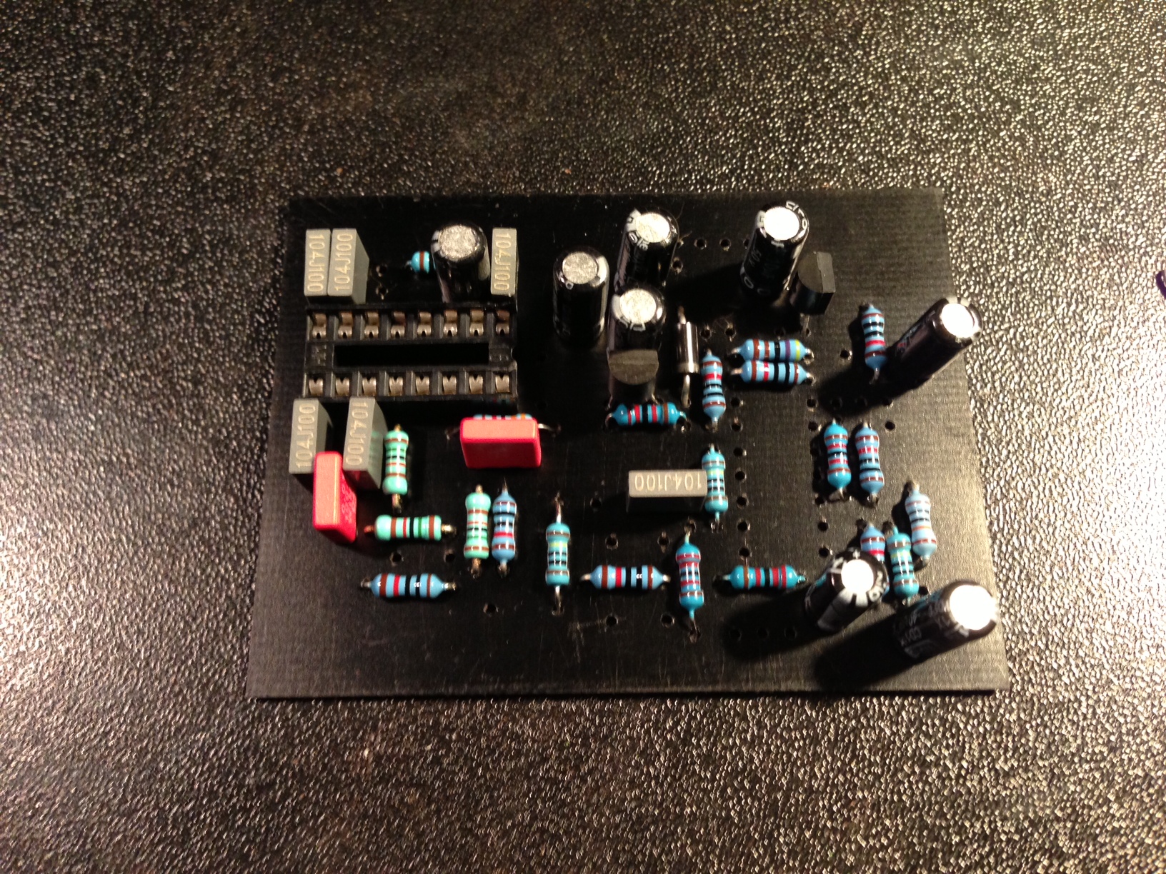
The board is now ready to populate with parts.

image_23


image_24

Updated Etching process

I wanted to share my current process for etching a PCB from scratch. Here is a list of supplies I used in this tutorial.

Items I needed:

  • Copper clad board (I use 1oz copper 030 thinkness, This might be to thin by some standards but it works well for me. I like to trim/cut my boards with household scisors.)
  • Laser Printer (HP LaserJet Pro P1102w with ePrint)
  • HP Glossy Presentation Paper (Office Depot/Max $6.99)
  • House hold iron (I use a Black & Decker household cloths iron)
  • Ferric chloride solution (You can get a bottle from Radio Shack that should last for  10-15 smaller PCBs)
  • Plastic containers with lids (Rubbermaid sandwich containers)
  • Drill Press or something of the like

Continue reading

Instant epic fail

When etching a face plate / name plate MAKE SURE you have your image flipped. I have been etching boards all day and when I made the face plate template in photoshop I did not have it flipped. Doesn’t work to well if you take a minute and think about it. Lesson learned.

20130311-000449.jpg

My hate for ironing

I love making PCBs at home.. but.. I hate the process of ironing the transfer on the copper clad board. I was searching for other ways of doing this and I have seen people use a laminator to do so but was unsure of the process. I have been digging around tonight and found that the “GBC laminator” can be modded to get higher temperatures to make sure the toner will adhere to the copper clad. Here the info I have found so far.

Different mods for laminators to help the process:

Looks like the desired laminator is the GBC-H220

I’m going to keep looking for more information. Looks like the H220 is a hard model to find since its an older model.

Update:

So I guess the GBC models are the most used because the came up with a new way of laminating. Here is a quote.

Instead of heater plates positioned after the transport rollers used to seal plastic pouches (like all other pouch laminators), the heaters in this redesign concept have been made into an arc and mounted above and below the two transport rollers. The heat is then radiated into the neoprene coated rollers very evenly as they continuously turn from the high-torque motor drive up to the correct temperature of 275ºF to 300ºF. In effect, GBC’s developers created a very inexpensive “hot roll” laminator!

Bit Sizes

Here are some standard hole sizes for DIY effects:

Drill Pilot Holes: 1/16″

  • 1/4″ Input/Output = 3/8″ hole
  • Toggle Switches = 1/4″ hole
  • 16mm Pots = 5/16″ hole
  • FootSwitch = 1/2″ hole
  • DC Power = 1/2″ hole


Big Muff Breakdown

I have been focusing on the older Electro-Harmonix Big Muffs the past few weeks and have compiled a list of changes between them. 90% of this information came from Kit’s Big Muff Pi History page

I essentially want to make one pedal that can switch between the Ram’s Head, V3 and the Russian. Here is what I got so far.

Clipping / Blocking Caps – These two caps determine the bandwidth to be clipped by the diodes in the two Clipping Stages, and have the most affect on the sound of the Big Muff.

Feedback / Filter Caps – They are responsible for how fizzy/buzzy a Big Muff will sound. Essentially they filter the amount of high frequencies in the bandwidth, determining if a Muff will sound more on the smooth side or the harsh side.

Tone Stack Filters – Big Muffs are known for their trademark mids scooped tones, meaning the mid frequencies are removed from the bandwidth, making the sound very deep and dark.

High Pass Filter – R5 / C9
Low Pass Filter – R8 / C8

Triangle:
Clipping / Blocking:
C6 .05uF, .1uF, .12uF, and 1.0uF
C7 .05uF, .1uF, .12uF, and 1.0uF
Feedback / Filter Caps:
C10 500pF, 560pF, 470pF
C11 500pF, 560pF, 470pF
C12 500pF, 560pF, 470pF
Tone Stack Filters:
C8 27k (Early), 33k (Common)
C9 27k (Early), 33k (Common)
R5
R8

Ram’s Head:
Clipping / Blocking:
C6 .047uF, .1uF, .12uF, and 1.0uF
C7 .047uF, .1uF, .12uF, and 1.0uF
Feedback / Filter Caps:
C10 560pF, 470pF
C11 560pF, 470pF
C12 560pF, 470pF
Tone Stack Filters:
C8 33k, 39k
C9 33k
R5
R8

V3:
Clipping / Blocking:
C6 1.0uF
C7 1.0uF
Feedback / Filter Caps:
C10 560pF, 470pF
C11 560pF, 470pF
C12 560pF, 470pF
Tone Stack Filters:
C8
C9 22k, 39k
R5
R8

Russian:
Clipping / Blocking:
C6 .047uF
C7 .047uF
Feedback / Filter Caps:
C10 430pF (Early), 500pF(the Civil War model), 470pF (green & black ver)
C11 430pF (Early), 500pF(the Civil War model), 470pF (green & black ver)
C12 430pF (Early), 500pF(the Civil War model), 470pF (green & black ver)
Tone Stack Filters:
C8 20k (Early), 22k (Black)
C9 22k
R5
R8


notes

  • Triangle version: R1=33k, C1=4n, R2=33k, C2=10n;
  • Ramshead version: R1=33k, C1=4n, R2=22k, C2=10n;
  • 1975 version: R1=39k, C1=4n, R2 = 22k, C2=10n;
  • 1977 opamp version (1): R1=5.6k, C1=100n, R2=1.2k, C2=120n;
  • 1977 opamp version (2): R1=8.2k, C1=100n, R2=1.2k, C2=120n;
  • Green Russian version: R1=20k, C1=3.9n, R2=22k, C2=10n;
  • Late model: R1=39k, C1=4n, R2=100k, C2=10n
  • Reissue version: R1=22k, C1=3.9n, R2=22k, C2=10n;
  • Little Big Muff version = reissue version.