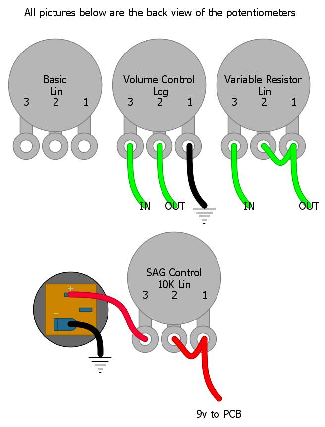
Potentiometers for the masses
I wanted to add this to my blog for reference and it may help some other “up and coming” builders like myself on their quest to making pedals. I drew this up in DIYLC.
I wanted to add this to my blog for reference and it may help some other “up and coming” builders like myself on their quest to making pedals. I drew this up in DIYLC.
I was working on a few Devi Ever clones and wanted to make 1 pedal that can be shaped into 3 different pedals. Devi is know for using 1 PCB for 3 or 4 pedals with just a few component changes. I wanted a way to wire a switch to change between 3 different capacitors or 3 different resistors. Here is what I have found.
I laid this out in DIYLC to give an example. The switch is a DPDT on-on-on Toggle Switch
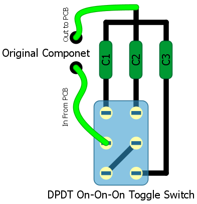
You will be able to do the same thing with resistors. Just replace C1-C3 with the needed resistor values.

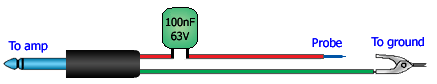
This is not a recap of the book Communion: A True Story (1987). This is some notes on audio probing and troubleshooting your circuit These are not my notes since I am trying to grasp how to accomplish this technique. I have just found notes from various places and I am archiving them here.
guitarmageddon Wrote:
OK, my world was turned upsidedown by the building of an Audio Probe. Can’t say enough good things about using one. Put simply, it lets you evesdrop on what’s happening at any given point in your circuit.
You need your guitar plugged in to the pedal, the pedal powered up and on and the amp on. The guitar needs to be producing sound. If you’ve got one, record something into a looper so you’ve got your hand(s) free.
The probe sheild is connected to the pedal earth (case or out put sleeve) and the tip goes to the amp’s input.
Start by strumming the guitar and touching the probe tip to the input jack tip. You should have signal as if in bypass.
Try the switch next, lug 4 (of the BYOC type bypass) should also have the input signal.
Now lug 5, the effect input, should still hear input signal.
After this it’ll get more interesting.Check your board’s input, then, followig the schematic, trace the audio path as it flows through the curcuit. listen to both sides of each componant. (Anything connected to ground will be silent on the earth side)
You should be able to hear changes, capacitors affecting the tone, resistors dampening the signal strength, etc, Transistors should amplify the signal from what it sounds like at the base, to what it sounds like at the collector. Don’t forget to listen to the pot lugs either.
Assuming your pedal produces no output, what you’re looking for is where the audio signal stops.If you’ve got some idea of where the problem might be, go straight to there and listen up and downstream.
Also, if things go dead inexplicably at some point, check that there isn’t a short to ground by using a DMM in continuity setting. Connect one probe to ground (screw hole of enclosure) and probe the signal path. Unless there’s a short, there shouldn’t be any continuity.
duhvoodooman Said:
When I first started using it, I found it much easier to understand the hook-up & function of a signal probe by thinking of it merely as a “movable output jack”. Plug your output cable into the jack of the signal tester, hook the black wire clip to ground (the solder tab for the sleeve of the input jack is always a good choice), and then touch the red probe to wherever in the circuit path you want to check.
more to come…
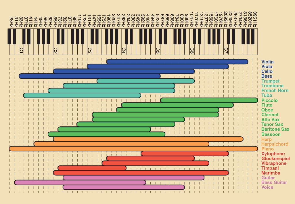
Found these on Google images and wanted to archive them.
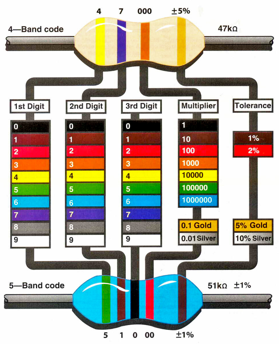

Found this to be useful.

I came across this chart and had to archive it. I just love things that are visually laid out like this.

Taken from GGG
| Stage Center Reverb |
|
Craig Anderton’s reverb unit that appeared in the September 1976 Guitar Player magazine. The layout is for a TL074 op amp type pinout instead of the RC4136 op amp originally specified. This circuit is powered by bipolar power supply, I have included a wiring diagram with a charge pump to allow power from a single nine-volt battery without sacrificing any headroom.
|
The two common ways to drive a reverb are current drive and voltage drive. With current drive the amount of *voltage drive* across the input terminals increases with frequency because the reverb inductance has an increasing impedance with frequency. Often with voltage drive the frequency response of the drive amplifier is shaped so it’s gain increases with frequency with an RC filter. If you use staight out voltage drive the current through the reverb input decreases with frequency which can sound a little rolled off. It’s not uncommon to roll-off the reverb with guitar. If you look at the center stage reverb the RC shaping parts are R4=22k and C4=20nF, so above frequency f = 1/(2*pi*22k*20nF) = 360Hz the voltage frequency response is flat.
The parts C1=220pF and R7=470k form a low pass filter will further adds to the roll-off, the cut-off for this filter is f=1/(2*pi*220p*470k) = 1.5kHz.
So all in all there’s a hell of a lot of roll-off compared to other designs – many designs have no roll-off or one roll-off at around 7kHz.
A simple mod to get rid of one roll-off would be to change C1 to 47pF.
Notes found around the interwebs that I want to keep track of.
Production years:
Tube layout: