11-8-2015 Update:
With OS X 10.11 El Capitan incorporating SIP (System Integrity Protection) it will break your previous install of PicKit2GUI. You will need to disable SIP before you can copy the needed files into the /bin/ directory to get PicKit2GUI to work again.
I found I also needed to install Java for OS X 2015-001 package first to get the JAVA runtime installed on OS X 10.11
Reboot your Mac into Recovery Mode by restarting your machine and holding down Command + R until you see the Apple logo. Then click Utilities > Terminal
In terminal window type the command: csrutil disable
Restart you Mac and SIP will be disabled. You are now able to re-copy over the pk2cmd and PK2DeviceFile.dat to the /bin/ directory.
Don’t forget to run: sudo chmod 777 /bin/PK2DeviceFile.dat
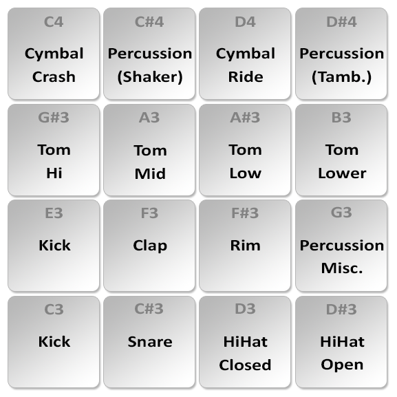
Recently I programmed 50 PIC16F684 chips to use ElectricDruid’s TAPLFO program. I have been asked by a few people how I burned the chips and with what. I decided the best thing to do was make a quick walk through.
Since I did all this on my Macbook Pro, this tutorial will be geared towards a Mac but the concept is the same with a PC.
Why did I need/want these chips?
There have been some great pedal DIY projects that use this chip to tap in a temp from a foot switch. Here is a small list of projects that use this chip and I am sure there are many more.
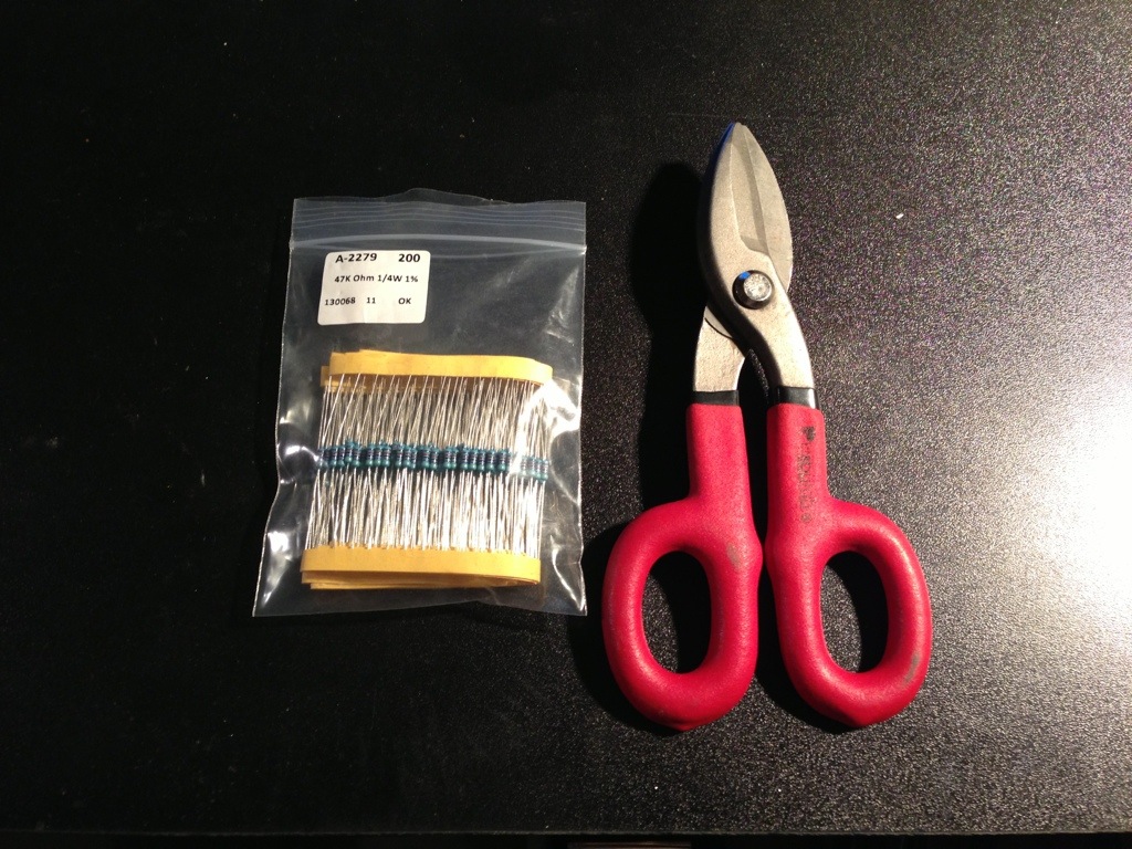
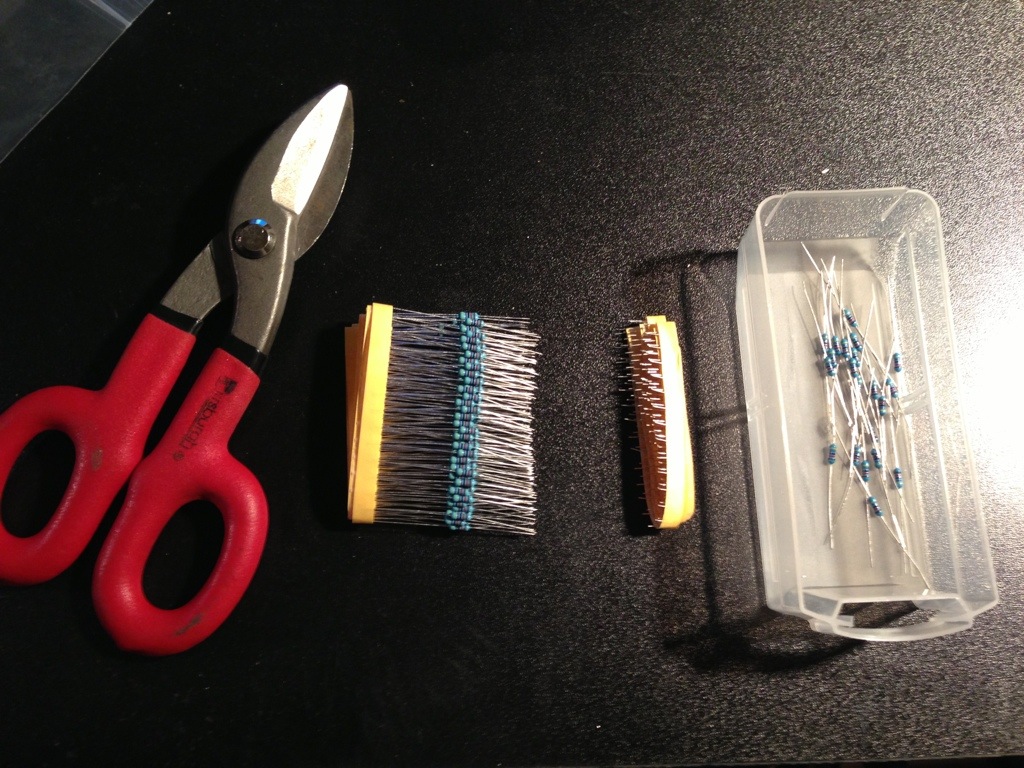
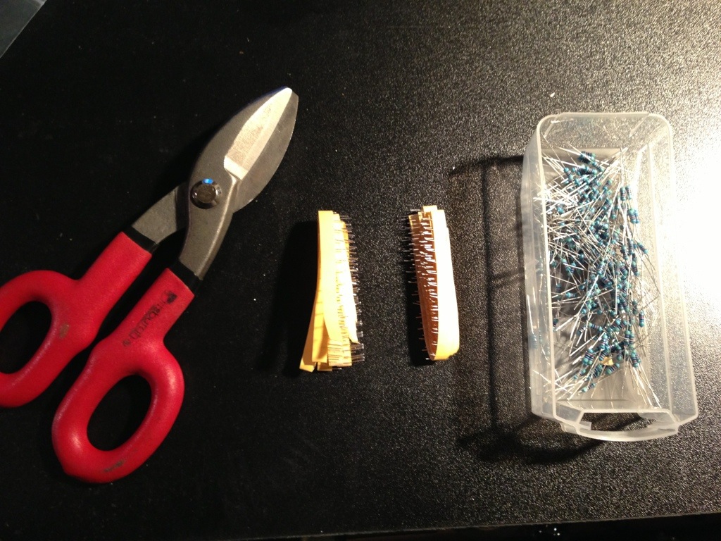
What I needed/what I had on hand?
PIC Chip – You will need a PIC16F684 You can pick them up at Mouser or try your luck with some China ones on eBay.
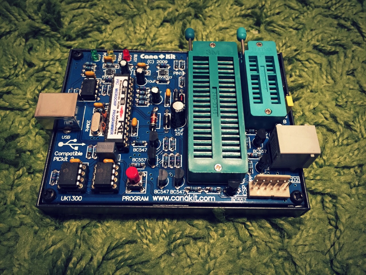
USB Programmer – There are so many programmers out there that it is impossible to cover them all. This is usually the biggest stumbling block when getting started. I went with the CanaKit UK1300 USB PIC Programmer (PicKit2 Clone) since it also meet my needs at work. I really like the fact that the sockets are on board and I do not need any accessories for it to program out of box.
Software – I really wanted to use MPLABX on my Mac but I had nothing but troubles trying to get it to recognize the CanaKit UK1300 so I went with using pk2cmd. When searching for command switches pk2cmd I came across a really nice Java GUI called PicKit2-Programmer-GUI that worked perfectly.
TAPLFO Program – ElectricDruid has this available on his website for private use only. If you like to use it commercially please contract Tom Wiltshire. Dpwnload the Assembled HEX code here.
My Programmer:
 To write the TAPLFO program to the chip do the following:
Hook up your programmer VIA USB. You should have some kind of status light on your programmer to let you know it is powered up.
Insert your PIC (PIC16F684 in this case) – This step can be done before or after the software is launched. I am asking for you to do it before we launch so you can see if PicKit2GUI detects the chip properly.
Launch the PicKit2GUI
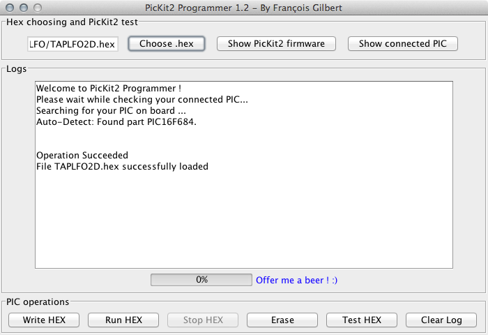
As you can see from the picture above the software detected that I have a PIC16F684 inserted (Auto-Detect: Found Part PIC16F684)
Load up the TAPLFO.hex file downloaded from Electric Druid into the PicKit2GUI software by pressing the “Choose .hex” button
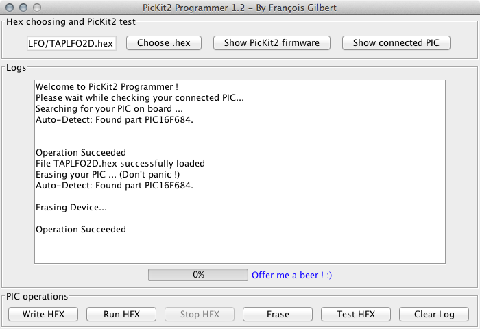
I always erase my PIC before any programing. I think its just a “best practice” and is most likely not necessary.
Erase:
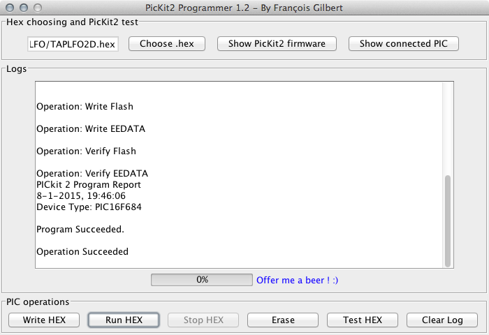
Write:
Now lets write the HEX file to the PIC16F684. Press the “Write Hex” button.
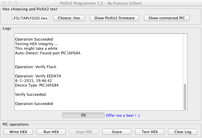
 Test Hex:
Another good practice is to test the HEX on the PIC to verify a working chip. Press the “Test HEX” button.
Now were are done. Just remove the PIC16F684 and place another in its place if you want to program more chips. There is no need to shut down the software or power off the programmer when changing the chips.
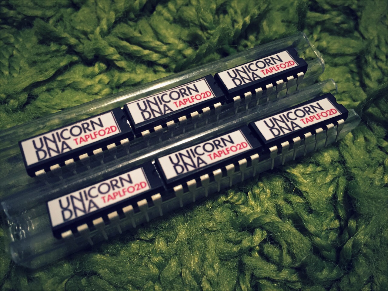
Now you can make some snazzy labels for your chips and get using them in your personal DIY projects.
Sticker Sizes: 16.34mm X 5mm 300DPI worked perfect for me. Print them on a full sheet of sticker paper and just cut them out as needed.
Here is a shot of some of my finished chips.